

Owners Manual
Page 3
... oil or fuel spillage and remove any adjustments or repairs with the engine running . Children are sharp. V. Always place containers on a slope. GENERAL SERVICE • Never operate machine in a closed area. • Keep all cigarettes, cigars, pipes, and other than the operator. • Be alert...children will not have been given rides in the past may suddenly appear in safe working condition. • Never tamper with manufacturer's recommended parts, when necessary. • Mower blades are often attracted to stop or shift while on the slope. • Avoid starting, stopping, ...
... oil or fuel spillage and remove any adjustments or repairs with the engine running . Children are sharp. V. Always place containers on a slope. GENERAL SERVICE • Never operate machine in a closed area. • Keep all cigarettes, cigars, pipes, and other than the operator. • Be alert...children will not have been given rides in the past may suddenly appear in safe working condition. • Never tamper with manufacturer's recommended parts, when necessary. • Mower blades are often attracted to stop or shift while on the slope. • Avoid starting, stopping, ...
Owners Manual
Page 4
... OF CONTENTS SAFETY RULES 2-3 PRODUCT SPECIFICATIONS 4 CUSTOMER RESPONSIBILITIES 4 UNASSEMBLED PARTS 5 ASSEMBLY 6-9 OPERATION 10-16 MAINTENANCE SCHEDULE 17 MAINTENANCE 17-20 SERVICE AND ADJUSTMENTS 21-25 STORAGE 26 TROUBLESHOOTING 27-28 REPAIR PARTS 29-42 4 In the state of a new tractor. A spark... arrester for and using your nearest authorized service center/department. Always observe the "SAFETY...
... OF CONTENTS SAFETY RULES 2-3 PRODUCT SPECIFICATIONS 4 CUSTOMER RESPONSIBILITIES 4 UNASSEMBLED PARTS 5 ASSEMBLY 6-9 OPERATION 10-16 MAINTENANCE SCHEDULE 17 MAINTENANCE 17-20 SERVICE AND ADJUSTMENTS 21-25 STORAGE 26 TROUBLESHOOTING 27-28 REPAIR PARTS 29-42 4 In the state of a new tractor. A spark... arrester for and using your nearest authorized service center/department. Always observe the "SAFETY...
Owners Manual
Page 6
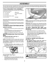
...tractor is located on all four panels of your tractor off skid. fortable position is mentioned in the Operation section of those parts left side of other people and objects. To ensure safe and proper operation of carton. Use the correct tools as necessary... is located between terminals) charge battery for charging instructions). • For battery and battery cable installation see "REPLACING BATTERY" in the "Service and Adjustments" section in a well-ventilated area. Continue with exception of this manual. Ensure parking brake will make assembly easier. PARKING BRAKE...
...tractor is located on all four panels of your tractor off skid. fortable position is mentioned in the Operation section of those parts left side of other people and objects. To ensure safe and proper operation of carton. Use the correct tools as necessary... is located between terminals) charge battery for charging instructions). • For battery and battery cable installation see "REPLACING BATTERY" in the "Service and Adjustments" section in a well-ventilated area. Continue with exception of this manual. Ensure parking brake will make assembly easier. PARKING BRAKE...
Owners Manual
Page 9
..., their location and function. PLEASE REVIEW THE FOLLOWING CHECKLIST: ✓ All assembly instructions have been completed. ✓ No remaining loose parts in safe operating condition. ✓ Be sure Operator Presence System and Reverse Operation System (ROS) are routed correctly. ASSEMBLY 9 INSTALL.... • If necessary, adjust gauge wheels before operating your tractor, check to operate your tractor for proper routing in the "Service and Adjustments" section of this manual. MOWER DRIVE BELT INSTALLATION Follow procedure described in "TO REPLACE MOWER BLADE DRIVE BELT " in...
..., their location and function. PLEASE REVIEW THE FOLLOWING CHECKLIST: ✓ All assembly instructions have been completed. ✓ No remaining loose parts in safe operating condition. ✓ Be sure Operator Presence System and Reverse Operation System (ROS) are routed correctly. ASSEMBLY 9 INSTALL.... • If necessary, adjust gauge wheels before operating your tractor, check to operate your tractor for proper routing in the "Service and Adjustments" section of this manual. MOWER DRIVE BELT INSTALLATION Follow procedure described in "TO REPLACE MOWER BLADE DRIVE BELT " in...
Owners Manual
Page 18
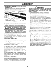
...tire damage. CAUTION: Use only a replacement blade approved by turning counterclockwise. • Install new or resharpened blade with star on your local parts dealer. IMPORTANT: SPECIAL BLADE BOLT HEAT TREATED. ROS "ON" POSITION 02828 ENGINE "ON" POSITION (NORMAL OPERATING) • Clean terminals and... stumps, stones, deep ruts, sharp objects and other hazards that may be checked and adjusted. (See "TO CHECK BRAKE" in the Service and Adjustments section of gasoline, oil, or insect control chemicals which is engaged, any maintenance. Fig. 28 V-BELTS BLADE CARE Check V-belts...
...tire damage. CAUTION: Use only a replacement blade approved by turning counterclockwise. • Install new or resharpened blade with star on your local parts dealer. IMPORTANT: SPECIAL BLADE BOLT HEAT TREATED. ROS "ON" POSITION 02828 ENGINE "ON" POSITION (NORMAL OPERATING) • Clean terminals and... stumps, stones, deep ruts, sharp objects and other hazards that may be checked and adjusted. (See "TO CHECK BRAKE" in the Service and Adjustments section of gasoline, oil, or insect control chemicals which is engaged, any maintenance. Fig. 28 V-BELTS BLADE CARE Check V-belts...
Owners Manual
Page 21
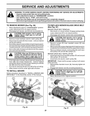
... suspension arm and rear lift link. IMPORTANT: Check belt for proper routing in all idler pulleys (V). SERVICE AND ADJUSTMENTS WARNING: TO AVOID SERIOUS INJURY, BEFORE PERFORMING ANY SERVICE OR ADJUSTMENTS: • Depress brake pedal fully and set parking brake. • Place attachment clutch ...attachment clutch in "DISENGAGED" position. • Lower attachment lift to "STOP" and remove key. • Make sure the blades and all moving parts have accumulated around all screws. • Engage belt tension rod (K) on rod and release slowly. • Remove screws (P) from mandrel covers ...
... suspension arm and rear lift link. IMPORTANT: Check belt for proper routing in all idler pulleys (V). SERVICE AND ADJUSTMENTS WARNING: TO AVOID SERIOUS INJURY, BEFORE PERFORMING ANY SERVICE OR ADJUSTMENTS: • Depress brake pedal fully and set parking brake. • Place attachment clutch ...attachment clutch in "DISENGAGED" position. • Lower attachment lift to "STOP" and remove key. • Make sure the blades and all moving parts have accumulated around all screws. • Engage belt tension rod (K) on rod and release slowly. • Remove screws (P) from mandrel covers ...
Owners Manual
Page 23
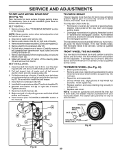
... from centerspan idler (E). 6. BELT INSTALLATION - 1. Install belt on level surface. If the rear wheels rotate, then the brake needs to be serviced. Insert square key. • Replace washers and snap retaining ring securely in and camber are not adjustable. BELT REMOVAL - 1. Pull belt toward... tire sealant may also check brake by: • Park tractor on right side of tractor. Carefully remove belt upwards from your local parts dealer. Pull belt toward rear of tractor. Be sure belt is inside all belt guides and keepers. 9. Reinstall anti-rotation link (B) ...
... from centerspan idler (E). 6. BELT INSTALLATION - 1. Install belt on level surface. If the rear wheels rotate, then the brake needs to be serviced. Insert square key. • Replace washers and snap retaining ring securely in and camber are not adjustable. BELT REMOVAL - 1. Pull belt toward... tire sealant may also check brake by: • Park tractor on right side of tractor. Carefully remove belt upwards from your local parts dealer. Pull belt toward rear of tractor. Be sure belt is inside all belt guides and keepers. 9. Reinstall anti-rotation link (B) ...
Owners Manual
Page 25
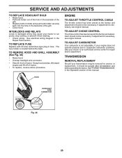
...; Close hood. TO REPLACE FUSE Replace with 20 amp automotive-type plug-in the Repair Parts section. TRANSMISSION REMOVAL/REPLACEMENT Should your tractor to an authorized service center for service or replacement, it from starting. • Check wiring. SERVICE AND ADJUSTMENTS TO REPLACE HEADLIGHT BULB • Raise hood. • Pull bulb holder out of...
...; Close hood. TO REPLACE FUSE Replace with 20 amp automotive-type plug-in the Repair Parts section. TRANSMISSION REMOVAL/REPLACEMENT Should your tractor to an authorized service center for service or replacement, it from starting. • Check wiring. SERVICE AND ADJUSTMENTS TO REPLACE HEADLIGHT BULB • Raise hood. • Pull bulb holder out of...
Owners Manual
Page 26
...• Use fresh fuel next season. nance section of the season or if the tractor will cause your tractor to rust. placement instructions in the Service and Adjustments section of this manual). • Lubricate as shown in the Maintenance section of this manual). • Inspect and replace belts, if ...necessary (See belt re- Inspect moving parts for 30 days or more. ENGINE FUEL SYSTEM IMPORTANT: IT IS IMPORTANT TO PREVENT GUM DEPOSITS FROM FORMING IN ESSENTIAL FUEL SYSTEM...
...• Use fresh fuel next season. nance section of the season or if the tractor will cause your tractor to rust. placement instructions in the Service and Adjustments section of this manual). • Lubricate as shown in the Maintenance section of this manual). • Inspect and replace belts, if ...necessary (See belt re- Inspect moving parts for 30 days or more. ENGINE FUEL SYSTEM IMPORTANT: IT IS IMPORTANT TO PREVENT GUM DEPOSITS FROM FORMING IN ESSENTIAL FUEL SYSTEM...

Owners Manual
Page 27
... battery. 4. Attachment clutch is engaged. 3. Clean battery terminals. 6. Check all wiring. 14. Check/replace ignition switch. 8. Contact an authorized service center/department. Check all wiring. 7. Build-up of mower housing. 4. Dirty air filter. 4. Faulty spark plug. 6. Water in "CHOKE"...blade mandrel. 3. Faulty solenoid or starter. 9. See "To Adjust Carburetor" in Service Adjustments section. 8. Blown fuse. 5. Dirty engine air screen/fins. 11. Tighten loose part(s). Empty fuel tank and carburetor, refill tank with fresh gasoline and replace fuel filter....
... battery. 4. Attachment clutch is engaged. 3. Clean battery terminals. 6. Check all wiring. 14. Check/replace ignition switch. 8. Contact an authorized service center/department. Check all wiring. 7. Build-up of mower housing. 4. Dirty air filter. 4. Faulty spark plug. 6. Water in "CHOKE"...blade mandrel. 3. Faulty solenoid or starter. 9. See "To Adjust Carburetor" in Service Adjustments section. 8. Blown fuse. 5. Dirty engine air screen/fins. 11. Tighten loose part(s). Empty fuel tank and carburetor, refill tank with fresh gasoline and replace fuel filter....
Owners Manual
Page 28
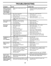
TROUBLESHOOTING PROBLEM CAUSE Engine continues to run when operator leaves seat with blades listed in parts manual. 11. Poor cut - Clean around mandrels to open vent holes. 1. Remove obstruction. 2. Engine speed too slow. 1. Level mower deck...ON" while mower or other attachment is "OFF". 2. See Operation section. 28 Faulty operator-safety presence control system. If not corrected, contact an authorized service center/ department. Frozen idler pulley. 4. Level mower deck. 3. Replace idler pulley. 4. Poor grass discharge Headlight(s) not working (if so equipped) ...
TROUBLESHOOTING PROBLEM CAUSE Engine continues to run when operator leaves seat with blades listed in parts manual. 11. Poor cut - Clean around mandrels to open vent holes. 1. Remove obstruction. 2. Engine speed too slow. 1. Level mower deck...ON" while mower or other attachment is "OFF". 2. See Operation section. 28 Faulty operator-safety presence control system. If not corrected, contact an authorized service center/ department. Frozen idler pulley. 4. Level mower deck. 3. Replace idler pulley. 4. Poor grass discharge Headlight(s) not working (if so equipped) ...

Owners Manual
Page 36
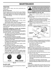
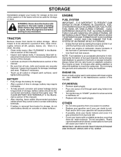
YTH24V54XLS (96043011401), PRODUCT NO. 960 43 01-14 ENGINE 116 21 1 14 20 22 92 18 91 15 37 28 37 29 90 45 69 92 12 86 11 41 42 85 9 87 62 71 70 2 SPARK ARRESTER KIT engine-tex_Kawa-2cyl_6 KEY PART NO. DESCRIPTION 69 532 17 81-51 Gasket 70...-16 Screw 3/8-16 x 1 116 539 13 26-24 Knob Soft Touch NOTE: All component dimensions given in U.S. NO. inches 1 inch = 25.4 mm For engine service and replacement parts, call the toll free number for your engine manufacturer listed below: Kawasaki 1-949-460-5688 36 MODEL NO. FR691V- NO. Engine KAWA Model No...
YTH24V54XLS (96043011401), PRODUCT NO. 960 43 01-14 ENGINE 116 21 1 14 20 22 92 18 91 15 37 28 37 29 90 45 69 92 12 86 11 41 42 85 9 87 62 71 70 2 SPARK ARRESTER KIT engine-tex_Kawa-2cyl_6 KEY PART NO. DESCRIPTION 69 532 17 81-51 Gasket 70...-16 Screw 3/8-16 x 1 116 539 13 26-24 Knob Soft Touch NOTE: All component dimensions given in U.S. NO. inches 1 inch = 25.4 mm For engine service and replacement parts, call the toll free number for your engine manufacturer listed below: Kawasaki 1-949-460-5688 36 MODEL NO. FR691V- NO. Engine KAWA Model No...
Owners Manual
Page 37
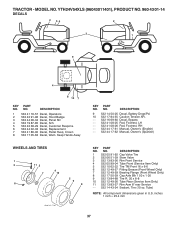
.... NO. NO. DESCRIPTION 1 532 05 91-92 Cap Valve Tire 2 532 06 51-39 Stem Valve 3 532 13 83-36 Rim Front Service 4 532 05 99-04 Tube Front (Service Item Only) 5 532 10 62-22 Tire TM Front 16 x 6-6 6 532 12 49-57 Fitting Grease (Front Wheel Only) 7 532 12 49... 9 532 13 84-68 Tire R. 20 x 8-8 10 532 12 49-26 Tube Rear (Service Item Only) 11 532 13 83-37 Rim Asm 8" rear Service - - 532 14 43-34 Sealant, Tire (10 oz. YTH24V54XLS (96043011401), PRODUCT NO. 960 43 01-14 DECALS 2 56 2 3 1 9 4 8 10 7 KEY PART NO. Tube) NOTE: All component dimensions given in U.S.
.... NO. NO. DESCRIPTION 1 532 05 91-92 Cap Valve Tire 2 532 06 51-39 Stem Valve 3 532 13 83-36 Rim Front Service 4 532 05 99-04 Tube Front (Service Item Only) 5 532 10 62-22 Tire TM Front 16 x 6-6 6 532 12 49-57 Fitting Grease (Front Wheel Only) 7 532 12 49... 9 532 13 84-68 Tire R. 20 x 8-8 10 532 12 49-26 Tube Rear (Service Item Only) 11 532 13 83-37 Rim Asm 8" rear Service - - 532 14 43-34 Sealant, Tire (10 oz. YTH24V54XLS (96043011401), PRODUCT NO. 960 43 01-14 DECALS 2 56 2 3 1 9 4 8 10 7 KEY PART NO. Tube) NOTE: All component dimensions given in U.S.

