

Owners Manual
Page 6
... is clear of this manual. ing your tractor for best cutting performance. • Reduce tire pressure to -rear for replacing motion and mower blade drive belts in carton. ✓ Battery is properly prepared and charged. ✓ Seat is adjusted comfortably and tightened securely. ✓ All...manual). CHECK FOR PROPER POSITION OF ALL BELTS See the figures that all connections are still secure and wires are routed properly around pulleys and inside all instructions in the Operation section of other people and objects. Correct tire pressure is important for the first time. ...
... is clear of this manual. ing your tractor for best cutting performance. • Reduce tire pressure to -rear for replacing motion and mower blade drive belts in carton. ✓ Battery is properly prepared and charged. ✓ Seat is adjusted comfortably and tightened securely. ✓ All...manual). CHECK FOR PROPER POSITION OF ALL BELTS See the figures that all connections are still secure and wires are routed properly around pulleys and inside all instructions in the Operation section of other people and objects. Correct tire pressure is important for the first time. ...

Owners Manual
Page 18
... brake. • Place attachment clutch in "DISENGAGED" position. • Turn ignition key to its lowest position. • Roll belt off engine pulley (M) and belt keepers (G). • Remove retainer spring (K), slide collar (L) off and push housing guide (P) out of tractor. TO INSTALL MOWER ...) Be sure tractor is on level surface and engage parking brake. • Lower attachment lift lever to "STOP" and remove key. • Make sure the blades and all moving parts have completely stopped. • Disconnect spark plug wire from rear mower bracket (D) - G M F R Q G A E B P C K...
... brake. • Place attachment clutch in "DISENGAGED" position. • Turn ignition key to its lowest position. • Roll belt off engine pulley (M) and belt keepers (G). • Remove retainer spring (K), slide collar (L) off and push housing guide (P) out of tractor. TO INSTALL MOWER ...) Be sure tractor is on level surface and engage parking brake. • Lower attachment lift lever to "STOP" and remove key. • Make sure the blades and all moving parts have completely stopped. • Disconnect spark plug wire from rear mower bracket (D) - G M F R Q G A E B P C K...
Owners Manual
Page 21
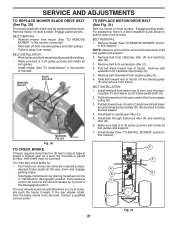
... remove from tractor (See "TO REMOVE MOWER" in this manual). SERVICE AND ADJUSTMENTS TO REPLACE MOWER BLADE DRIVE BELT (See Fig. 30) The mower blade drive belt may also check brake by placing freewheel control in all pulley grooves and inside the belt keeper. 4. If the rear wheels rotate, then the brake needs...
... remove from tractor (See "TO REMOVE MOWER" in this manual). SERVICE AND ADJUSTMENTS TO REPLACE MOWER BLADE DRIVE BELT (See Fig. 30) The mower blade drive belt may also check brake by placing freewheel control in all pulley grooves and inside the belt keeper. 4. If the rear wheels rotate, then the brake needs...

Owners Manual
Page 26
... attachment is engaged. 1. TROUBLESHOOTING POINTS PROBLEM CAUSE Engine continues to ROS "ON" position. CORRECTION 1. uneven Mower blades will not charge 1. Frozen idler pulley. 4. Level mower deck. 3. Clean around mandrels. 1. Poor grass discharge Headlight(s) not working (if so equipped... WHEEL" in "disengaged" position. 2. Bent blade mandrel. 5. Clogged mower deck vent holes from buildup 11. Worn/damaged mower drive belt. 3. Replace idler pulley. 4. Replace mower drive belt. 9. Worn, bent or loose blade. 2. Mower drive belt worn. 8. Freewheel ...
... attachment is engaged. 1. TROUBLESHOOTING POINTS PROBLEM CAUSE Engine continues to ROS "ON" position. CORRECTION 1. uneven Mower blades will not charge 1. Frozen idler pulley. 4. Level mower deck. 3. Clean around mandrels. 1. Poor grass discharge Headlight(s) not working (if so equipped... WHEEL" in "disengaged" position. 2. Bent blade mandrel. 5. Clogged mower deck vent holes from buildup 11. Worn/damaged mower drive belt. 3. Replace idler pulley. 4. Replace mower drive belt. 9. Worn, bent or loose blade. 2. Mower drive belt worn. 8. Freewheel ...
Owners Manual
Page 39
...Keeper Belt Pulley Idler Spring...30-03 Bolt/Washer asm 7/16-20 unf 11 532 40 53-80 Blade Mower Hi Lift 13 532 19 28-72 Shaft Assembly, Mandrel 14 532 ... 31 532 18 76-90 Washer, Spacer 32 532 19 74-73 Pulley, Mandrel 33 532 40 02-34 Nut, Toplock, Flanged 34 872 11 ...Bolt Carr Sh. 3/8-16 x 1-1/2 Gr. 5 36 532 19 73-79 Pulley, Idler, Flat 37 819 13 13-16 Washer 13/32 x 13/16... Port Quick Connect Coupling Mandrel Assembly (Includes housing, shaft assembly, and bearing only - pulley/nut/washer and blade bolt/washers not included) Replacement Mower, Complete NOTE: All component dimensions given in U.S. ...
...Keeper Belt Pulley Idler Spring...30-03 Bolt/Washer asm 7/16-20 unf 11 532 40 53-80 Blade Mower Hi Lift 13 532 19 28-72 Shaft Assembly, Mandrel 14 532 ... 31 532 18 76-90 Washer, Spacer 32 532 19 74-73 Pulley, Mandrel 33 532 40 02-34 Nut, Toplock, Flanged 34 872 11 ...Bolt Carr Sh. 3/8-16 x 1-1/2 Gr. 5 36 532 19 73-79 Pulley, Idler, Flat 37 819 13 13-16 Washer 13/32 x 13/16... Port Quick Connect Coupling Mandrel Assembly (Includes housing, shaft assembly, and bearing only - pulley/nut/washer and blade bolt/washers not included) Replacement Mower, Complete NOTE: All component dimensions given in U.S. ...

Parts List
Page 14
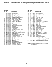
...Front RH Washer 13/32 x 1 x 1/2 11 Ga. NO. TRACTOR - - RH Keeper Belt Pulley Idler Spring Return Cable Clutch Manual w/Spr. pulley/nut/washer and blade bolt/washers not included) Replacement Mower, Complete NOTE: All component dimensions given in U.S. LH Keeper Belt ... # 10 x 0.750 8 532 19 30-03 Bolt/Washer asm 7/16-20 unf 11 532 40 53-80 Blade Mower Hi Lift 13 532 19 28-72 Shaft Assembly, Mandrel 14 532 18 72-81 Housing, Mandrel 15 532 ...3/4 Washer 13/32 x 13/16 x 12 Ga. inches 1 inch = 25.4 mm 39 MODEL NUMBER YTH21K46 (96045002601), PRODUCT NO. 960 45 00-26 MOWER DECK KEY PART NO.
...Front RH Washer 13/32 x 1 x 1/2 11 Ga. NO. TRACTOR - - RH Keeper Belt Pulley Idler Spring Return Cable Clutch Manual w/Spr. pulley/nut/washer and blade bolt/washers not included) Replacement Mower, Complete NOTE: All component dimensions given in U.S. LH Keeper Belt ... # 10 x 0.750 8 532 19 30-03 Bolt/Washer asm 7/16-20 unf 11 532 40 53-80 Blade Mower Hi Lift 13 532 19 28-72 Shaft Assembly, Mandrel 14 532 18 72-81 Housing, Mandrel 15 532 ...3/4 Washer 13/32 x 13/16 x 12 Ga. inches 1 inch = 25.4 mm 39 MODEL NUMBER YTH21K46 (96045002601), PRODUCT NO. 960 45 00-26 MOWER DECK KEY PART NO.


