
Owners Manual
Page 6
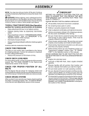
... Adjustments section of this manual. Ensure tractor is adjusted comfortably and tightened securely. ✓ All tires are properly clamped. ✓ Before driving tractor, be properly leveled. See "TO LEVEL MOWER" in the Opera- CHECK FOR PROPER POSITION OF ALL BELTS See the figures that the... • Reduce tire pressure to purge the transmission before you learn how to operate your tractor for leveling). ✓ Check mower and drive belts. See that follow . Correct tire pressure is in the Operation section of this manual. ✓CHECKLIST BEFORE YOU OPERATE YOUR NEW ...
... Adjustments section of this manual. Ensure tractor is adjusted comfortably and tightened securely. ✓ All tires are properly clamped. ✓ Before driving tractor, be properly leveled. See "TO LEVEL MOWER" in the Opera- CHECK FOR PROPER POSITION OF ALL BELTS See the figures that the... • Reduce tire pressure to purge the transmission before you learn how to operate your tractor for leveling). ✓ Check mower and drive belts. See that follow . Correct tire pressure is in the Operation section of this manual. ✓CHECKLIST BEFORE YOU OPERATE YOUR NEW ...
Owners Manual
Page 9
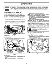
... running , any adjustments or repairs. CAUTION: Always stop mower blades, place attachment clutch control in brake position. To eliminate this possibility, always stop ground drive, depress brake pedal all the way down . • Move motion control lever (J) to "STOP" position and remove key. HOW TO USE YOUR TRACTOR... reduces engine's operating efficiency. • Full speed (fast) offers the best mower performance. D ( ) ATTACHMENT CLUTCH LEVER "DISENGAGED" ( ) ATTACHMENT CLUTCH LEVER "ENGAGED" Fig. 5 GROUND DRIVE • To stop engine when stopping tractor on grass areas.
... running , any adjustments or repairs. CAUTION: Always stop mower blades, place attachment clutch control in brake position. To eliminate this possibility, always stop ground drive, depress brake pedal all the way down . • Move motion control lever (J) to "STOP" position and remove key. HOW TO USE YOUR TRACTOR... reduces engine's operating efficiency. • Full speed (fast) offers the best mower performance. D ( ) ATTACHMENT CLUTCH LEVER "DISENGAGED" ( ) ATTACHMENT CLUTCH LEVER "ENGAGED" Fig. 5 GROUND DRIVE • To stop engine when stopping tractor on grass areas.
Owners Manual
Page 11
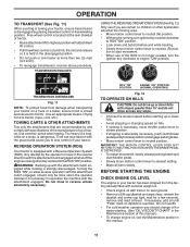
...ENGINE OIL LEVEL The engine in the disengaged position. • Do not push or tow tractor at more than 15° and do not drive across any slope. • Choose the slowest speed before and while backing. • Slowly move motion control lever to allow reverse operation with...seconds, remove and read oil level. ROS "ON" POSITION 02828 ENGINE "ON" POSITION (NORMAL OPERATING) Fig. 12 TO OPERATE ON HILLS CAUTION: Do not drive up with a Reverse Operation System (ROS). IMPORTANT: THE MOTION CONTROL LEVER DOES NOT RETURN TO NEUTRAL POSITION WHEN THE BRAKE PEDAL IS DEPRESSED. • ...
...ENGINE OIL LEVEL The engine in the disengaged position. • Do not push or tow tractor at more than 15° and do not drive across any slope. • Choose the slowest speed before and while backing. • Slowly move motion control lever to allow reverse operation with...seconds, remove and read oil level. ROS "ON" POSITION 02828 ENGINE "ON" POSITION (NORMAL OPERATING) Fig. 12 TO OPERATE ON HILLS CAUTION: Do not drive up with a Reverse Operation System (ROS). IMPORTANT: THE MOTION CONTROL LEVER DOES NOT RETURN TO NEUTRAL POSITION WHEN THE BRAKE PEDAL IS DEPRESSED. • ...
Owners Manual
Page 12
...parking brake. • Place motion control lever in minimizing the formation of 30 days or longer. AUTOMATIC TRANSMISSION WARM UP • Before driving the unit in neutral. If the engine does not start after adding stabilizer to allow the stabilizer to choke position. WARM WEATHER STARTING ... as soon as described above ) • When engine starts, move throttle control to the fast position. • The attachments and ground drive can also be used during storage. Do not run until the engine runs roughly, then move the throttle control to fast position. Purchase fuel...
...parking brake. • Place motion control lever in minimizing the formation of 30 days or longer. AUTOMATIC TRANSMISSION WARM UP • Before driving the unit in neutral. If the engine does not start after adding stabilizer to allow the stabilizer to choke position. WARM WEATHER STARTING ... as soon as described above ) • When engine starts, move throttle control to the fast position. • The attachments and ground drive can also be used during storage. Do not run until the engine runs roughly, then move the throttle control to fast position. Purchase fuel...
Owners Manual
Page 13
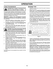
...After the tractor moves approximately five (5) feet (1,5 m) return the motion control lever to full reverse position and hold for trimming. • Drive so that clippings are discharged onto the area that will suit the terrain and give best performance of your tractor. Repeat this procedure three ... attached to the desired height. • Do not mow grass when it should be movement of clippings and more even distribution of the drive wheels. 4. Repeat this procedure with engine off engine and set . 2. Your transmission is running , move throttle control to ensure better ...
...After the tractor moves approximately five (5) feet (1,5 m) return the motion control lever to full reverse position and hold for trimming. • Drive so that clippings are discharged onto the area that will suit the terrain and give best performance of your tractor. Repeat this procedure three ... attached to the desired height. • Do not mow grass when it should be movement of clippings and more even distribution of the drive wheels. 4. Repeat this procedure with engine off engine and set . 2. Your transmission is running , move throttle control to ensure better ...
Owners Manual
Page 17
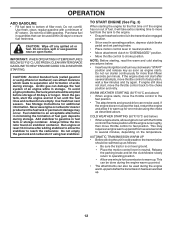
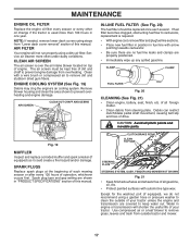
... and trash from overheating. Remove blower housing and clean the area shown to carburetor, replacement is over the air intake blower located on top of drive. If fuel filter becomes clogged, obstructing fuel flow to prevent overheating and engine damage. AIR SCREEN CLEAN OUT CHAFF AND DEBRIS 02744 Fig. 19 MUFFLER...
... and trash from overheating. Remove blower housing and clean the area shown to carburetor, replacement is over the air intake blower located on top of drive. If fuel filter becomes clogged, obstructing fuel flow to prevent overheating and engine damage. AIR SCREEN CLEAN OUT CHAFF AND DEBRIS 02744 Fig. 19 MUFFLER...
Owners Manual
Page 18
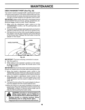
.... • Plug any holes in the operator's position with your garden hose. 4. Turn the ignition key to the STOP position to a level, clear spot on . 6. Drive the tractor to turn the tractor's engine off . 9. Thread the nozzle adapter (packaged with the cutting deck engaged until the deck is cleaned. 8. Turn the...
.... • Plug any holes in the operator's position with your garden hose. 4. Turn the ignition key to the STOP position to a level, clear spot on . 6. Drive the tractor to turn the tractor's engine off . 9. Thread the nozzle adapter (packaged with the cutting deck engaged until the deck is cleaned. 8. Turn the...
Owners Manual
Page 22
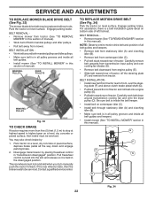
...TO REMOVE MOWER" in this manual). Disengage transmission by : 1. The rear wheels must be serviced. Contact a qualified service center. TO REPLACE MOTION DRIVE BELT (See Fig. 34) Park the tractor on level surface. ing plate (F) and above clutch brake pedal shaft (G). • Pull belt toward... and keepers. • Remove belt from stationary idler (A) and clutching idler (B). • Remove belt from tractor. NOTE: Observe entire motion drive belt and position of all belt guides and keepers. • Install mower (See "TO INSTALL MOWER" section in this section of manual). For...
...TO REMOVE MOWER" in this manual). Disengage transmission by : 1. The rear wheels must be serviced. Contact a qualified service center. TO REPLACE MOTION DRIVE BELT (See Fig. 34) Park the tractor on level surface. ing plate (F) and above clutch brake pedal shaft (G). • Pull belt toward... and keepers. • Remove belt from stationary idler (A) and clutching idler (B). • Remove belt from tractor. NOTE: Observe entire motion drive belt and position of all belt guides and keepers. • Install mower (See "TO INSTALL MOWER" section in this section of manual). For...
Owners Manual
Page 27
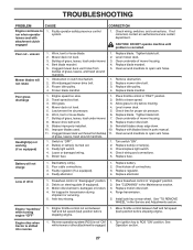
...1. Clean around mandrels. 1. Check wiring and connections. 5. Replace battery. 2. Air trapped in parts manual. 11. Replace motion drive belt. 4. Reverse operation system (ROS) is shifted into reverse 1. Poor cut - Obstruction in the Maintenance section. 3. Replace ...blade. Clean underside of mower housing. 8. Replace mower drive belt. 3. Mower deck not level. 4. Blades improperly installed. 9. Bad battery cell(s). 2. Motion drive belt worn, damaged, or broken. 4. Engine throttle control not set between ...
...1. Clean around mandrels. 1. Check wiring and connections. 5. Replace battery. 2. Air trapped in parts manual. 11. Replace motion drive belt. 4. Reverse operation system (ROS) is shifted into reverse 1. Poor cut - Obstruction in the Maintenance section. 3. Replace ...blade. Clean underside of mower housing. 8. Replace mower drive belt. 3. Mower deck not level. 4. Blades improperly installed. 9. Bad battery cell(s). 2. Motion drive belt worn, damaged, or broken. 4. Engine throttle control not set between ...
Owners Manual
Page 29
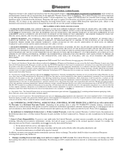
...Stratton, Honda, Kawasaki, or Kohler (Husqvarna does handle warranty issues on ExhibitA, Transmission / Transaxle (including Drive Systems) are excluded from the date of purchase. THIS WARRANTY IS GIVEN ONLY BY HUSQVARNA, AND MAY BE MODIFIED ONLY BY HUSQVARNA. AS SUCH, SOME OF THE ...material or workmanship under this Limited Warranty, you purchased the unit from defects in those separate warranties. Please refer to Husqvarna. Under this Husqvarna® product is not authorized to the limitations and exclusions described below. Products are NOT covered. Owner's (Your...
...Stratton, Honda, Kawasaki, or Kohler (Husqvarna does handle warranty issues on ExhibitA, Transmission / Transaxle (including Drive Systems) are excluded from the date of purchase. THIS WARRANTY IS GIVEN ONLY BY HUSQVARNA, AND MAY BE MODIFIED ONLY BY HUSQVARNA. AS SUCH, SOME OF THE ...material or workmanship under this Limited Warranty, you purchased the unit from defects in those separate warranties. Please refer to Husqvarna. Under this Husqvarna® product is not authorized to the limitations and exclusions described below. Products are NOT covered. Owner's (Your...
Parts Manual
Page 8
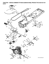
MODEL NUMBER YTH18542 (96043018400), PRODUCT NO. 960 43 01-84 DRIVE 70 56 74 185 143 221 184 35 42 64 167 159 160 29 159 15 49 17 190 52 51 188 185 186 189 187 50 51 2 116 216 125 80 125 121 170 231 51 211 166 161 178 153 23 175 114 122 176 174 233 232 22 160 166 279 116 73 99 1 73 2 183 205 33 37 8 drive-tex_T2_fender_29 TRACTOR - -
MODEL NUMBER YTH18542 (96043018400), PRODUCT NO. 960 43 01-84 DRIVE 70 56 74 185 143 221 184 35 42 64 167 159 160 29 159 15 49 17 190 52 51 188 185 186 189 187 50 51 2 116 216 125 80 125 121 170 231 51 211 166 161 178 153 23 175 114 122 176 174 233 232 22 160 166 279 116 73 99 1 73 2 183 205 33 37 8 drive-tex_T2_fender_29 TRACTOR - -
Parts Manual
Page 9
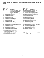
... Shift Spring Shift Spacer Axle Handle Parking Brake Bolt Spacer Retainer Washer Link Clutch Ground Drive Bellcrank Ground Drive Keeper Bellcrank Ground Drive Washer 25/32 x 1-5/8 x 16 Ga. Bushing Shaft Bracket Pulley Idler Retainer Spring... component dimensions given in U.S. Cover, Foot Pedal Bolt Pulley Idler Flat Lock Nut 3/8-16 Idler V-Groove Offset V-Belt, Drive Shaft Asm. TRACTOR - - Pedal Brake Control Console Bolt Hex 5/16-18 Gr. 5 Screw 1/4 x 1/2 Strap ... KEY PART NO. inches 1 inch = 25.4 mm 9 MODEL NUMBER YTH18542 (96043018400), PRODUCT NO. 960 43 01-84 DRIVE KEY PART NO.
... Shift Spring Shift Spacer Axle Handle Parking Brake Bolt Spacer Retainer Washer Link Clutch Ground Drive Bellcrank Ground Drive Keeper Bellcrank Ground Drive Washer 25/32 x 1-5/8 x 16 Ga. Bushing Shaft Bracket Pulley Idler Retainer Spring... component dimensions given in U.S. Cover, Foot Pedal Bolt Pulley Idler Flat Lock Nut 3/8-16 Idler V-Groove Offset V-Belt, Drive Shaft Asm. TRACTOR - - Pedal Brake Control Console Bolt Hex 5/16-18 Gr. 5 Screw 1/4 x 1/2 Strap ... KEY PART NO. inches 1 inch = 25.4 mm 9 MODEL NUMBER YTH18542 (96043018400), PRODUCT NO. 960 43 01-84 DRIVE KEY PART NO.


