
Owners Manual
Page 6
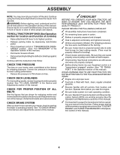
...section for the first time. Verify that the brake is operating properly. Operate them before operating your tractor, check to see that the belts are routed properly around pulleys and inside all controls, their location and function. eration System (ROS) are properly inflated. (For shipping ... SYSTEM After you start the engine. ✓ Be sure brake system is at the factory for leveling). ✓ Check mower and drive belts. PORT" in the Operation section of this manual. WARNING: Before starting and transmission purging instructions (See "TO START ENGINE" and "PURGE ...
...section for the first time. Verify that the brake is operating properly. Operate them before operating your tractor, check to see that the belts are routed properly around pulleys and inside all controls, their location and function. eration System (ROS) are properly inflated. (For shipping ... SYSTEM After you start the engine. ✓ Be sure brake system is at the factory for leveling). ✓ Check mower and drive belts. PORT" in the Operation section of this manual. WARNING: Before starting and transmission purging instructions (See "TO START ENGINE" and "PURGE ...
Owners Manual
Page 14
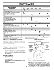
... not cover items that have been subjected to see if you should replace the spark plug, clean or replace air filter, and check blades and belts for wear. Change more often when operating under a heavy load or in Maintenance Section. MAINTENANCE MAINTENANCE SCHEDULE BEFORE EACH USE EVERY 8 HOURS EVERY .../Replace Mower Blades 3 T Lubrication Chart 0 Check Battery Level 4 R Clean Battery and Terminals Clean Debris Off Steering Plate 5 Check Transaxle Cooling Check Mower Levelness Check V-Belts Check Engine Oil Level Change Engine Oil (models with maintenance-free battery. 5 -
... not cover items that have been subjected to see if you should replace the spark plug, clean or replace air filter, and check blades and belts for wear. Change more often when operating under a heavy load or in Maintenance Section. MAINTENANCE MAINTENANCE SCHEDULE BEFORE EACH USE EVERY 8 HOURS EVERY .../Replace Mower Blades 3 T Lubrication Chart 0 Check Battery Level 4 R Clean Battery and Terminals Clean Debris Off Steering Plate 5 Check Transaxle Cooling Check Mower Levelness Check V-Belts Check Engine Oil Level Change Engine Oil (models with maintenance-free battery. 5 -
Owners Manual
Page 16
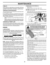
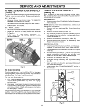
... • 16 Fig.18 Slide oil drain extension under front end of oil drain extension. Check your nearest authorized service center/department. The belts are not broken. • Slide lower dash cover up with engine side wall. ENGINE LUBRICATION Only use compressed air or high pressure sprayer to... use high pressure water or steam to clean transmission. • Inspect cooling fan to be kept clean to clean cooling fins. MAINTENANCE V-BELTS Check V-belts for deterioration and wear after every 50 hours of operation or at least • once a year if the tractor is not used above...
... • 16 Fig.18 Slide oil drain extension under front end of oil drain extension. Check your nearest authorized service center/department. The belts are not broken. • Slide lower dash cover up with engine side wall. ENGINE LUBRICATION Only use compressed air or high pressure sprayer to... use high pressure water or steam to clean transmission. • Inspect cooling fan to be kept clean to clean cooling fins. MAINTENANCE V-BELTS Check V-belts for deterioration and wear after every 50 hours of operation or at least • once a year if the tractor is not used above...
Owners Manual
Page 17
..., whichever occurs first. of this manual. Use compressed air or a leaf blower to keep water out. Debris can restrict clutch/brake pedal shaft movement, causing belt slip and loss of your tractor unless the engine and transmission are covered to remove grass, leaves and trash from "Lower dash cover removal" section...
..., whichever occurs first. of this manual. Use compressed air or a leaf blower to keep water out. Debris can restrict clutch/brake pedal shaft movement, causing belt slip and loss of your tractor unless the engine and transmission are covered to remove grass, leaves and trash from "Lower dash cover removal" section...
Owners Manual
Page 19
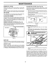
... motion control lever in neutral position. • Place attachment clutch in "DISENGAGED" position. • Turn ignition key to its lowest position. • Roll belt off engine pulley (M) and belt keepers (G). • Remove retainer spring (K), slide collar (L) off and push housing guide (P) out of bracket. • Remove clutch cable spring (Q) from idler arm...
... motion control lever in neutral position. • Place attachment clutch in "DISENGAGED" position. • Turn ignition key to its lowest position. • Roll belt off engine pulley (M) and belt keepers (G). • Remove retainer spring (K), slide collar (L) off and push housing guide (P) out of bracket. • Remove clutch cable spring (Q) from idler arm...
Owners Manual
Page 20
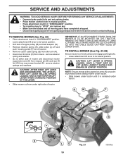
...and position slot in the Operation section of clutch cable spring (Q) into hole in idler arm (R). • Push clutch cable housing guide (P) into hole in belt keepers (G). G M F G A E B P C K LD Fig. 28 20 Work from left side of link assembly through front hole in tractor .... 24 • ATTACH REAR LIFT LINKS (C) - M C D Fig. 25 • ATTACH FRONT LINK (E) - R Q Fig. 27 IMPORTANT: CHECK BELT FOR PROPER ROUTING IN ALL MOWER PULLEY GROOVES. • Raise attachment lift lever to highest position. • If necessary, adjust gauge wheels before operating mower...
...and position slot in the Operation section of clutch cable spring (Q) into hole in idler arm (R). • Push clutch cable housing guide (P) into hole in belt keepers (G). G M F G A E B P C K LD Fig. 28 20 Work from left side of link assembly through front hole in tractor .... 24 • ATTACH REAR LIFT LINKS (C) - M C D Fig. 25 • ATTACH FRONT LINK (E) - R Q Fig. 27 IMPORTANT: CHECK BELT FOR PROPER ROUTING IN ALL MOWER PULLEY GROOVES. • Raise attachment lift lever to highest position. • If necessary, adjust gauge wheels before operating mower...
Owners Manual
Page 22
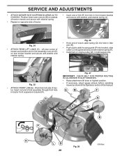
...pulley and over the steer- Be sure belt is inside the belt keeper. • Install belt on centerspan idler (C). • Install belt through stationary idler (A) and clutching idler (B). • Make sure belt is a belt installation guide decal on bottom side of manual). BELT REMOVAL • Remove mower from tractor ...and remove from mower. Park the tractor on level surface. SERVICE AND ADJUSTMENTS TO REPLACE MOWER BLADE DRIVE BELT (See Fig. 33) The mower blade drive belt may also check brake by placing freewheel control in highest gear on a level, dry concrete or paved ...
...pulley and over the steer- Be sure belt is inside the belt keeper. • Install belt on centerspan idler (C). • Install belt through stationary idler (A) and clutching idler (B). • Make sure belt is a belt installation guide decal on bottom side of manual). BELT REMOVAL • Remove mower from tractor ...and remove from mower. Park the tractor on level surface. SERVICE AND ADJUSTMENTS TO REPLACE MOWER BLADE DRIVE BELT (See Fig. 33) The mower blade drive belt may also check brake by placing freewheel control in highest gear on a level, dry concrete or paved ...
Owners Manual
Page 25
... plug(s). Store in a clean, dry area. • Clean entire tractor. (See "CLEANING" in the Maintenance section of this manual.) • Inspect and replace belts, if necessary. (See belt replacement instructions in storage, battery may reach an open flame or spark. NOTE: Fuel stabilizer is equipped with gasoline in the tank inside a building...
... plug(s). Store in a clean, dry area. • Clean entire tractor. (See "CLEANING" in the Maintenance section of this manual.) • Inspect and replace belts, if necessary. (See belt replacement instructions in storage, battery may reach an open flame or spark. NOTE: Fuel stabilizer is equipped with gasoline in the tank inside a building...
Owners Manual
Page 27
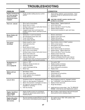
...or lamp(s). 3. Air trapped in clutch mechanism. 2. Place freewheel control in "disengaged" position. 2. Replace blade. Replace mower drive belt. 9. Replace fuse. Freewheel control in "engaged" position. 2. Engine dies when tractor is not "ON" 1. Faulty operator-safety ... 2. Buildup of drive 1. Clean around mandrels. 1. Faulty alternator. 1. Replace idler pulley. 4. Wet grass. 3. Replace motion drive belt. 4. If not corrected, contact an authorized service center/ department. Clogged mower deck vent holes from buildup 11. Replace blade mandrel. ...
...or lamp(s). 3. Air trapped in clutch mechanism. 2. Place freewheel control in "disengaged" position. 2. Replace blade. Replace mower drive belt. 9. Replace fuse. Freewheel control in "engaged" position. 2. Engine dies when tractor is not "ON" 1. Faulty operator-safety ... 2. Buildup of drive 1. Clean around mandrels. 1. Faulty alternator. 1. Replace idler pulley. 4. Wet grass. 3. Replace motion drive belt. 4. If not corrected, contact an authorized service center/ department. Clogged mower deck vent holes from buildup 11. Replace blade mandrel. ...
Owners Manual
Page 29
...thirty days of the other limitations apply, as otherwise directed in the operator's manual. Preventative maintenance as throttle cable, belt guides adjustments; Damages resulting from coverage, and other manufacturers' engines under normal use will assign the transmission / transaxle ...LIMITATION OF INCIDENTAL OR CONSEQUENTIAL DAMAGES. Except where otherwise indicated on engines manufactured by law. Husqvarna will result in this Husqvarna® product. Husqvarna is offered instead of this document. Depending on transmissions or transaxles. Please refer to the...
...thirty days of the other limitations apply, as otherwise directed in the operator's manual. Preventative maintenance as throttle cable, belt guides adjustments; Damages resulting from coverage, and other manufacturers' engines under normal use will assign the transmission / transaxle ...LIMITATION OF INCIDENTAL OR CONSEQUENTIAL DAMAGES. Except where otherwise indicated on engines manufactured by law. Husqvarna will result in this Husqvarna® product. Husqvarna is offered instead of this document. Depending on transmissions or transaxles. Please refer to the...
Owners Manual
Page 30
... you to register your product online at www.husqvarna.com. 11. Reinforced Stamped (Armor Protected) 10 Year Limited & Fabricated Limited Lifetime, Deck Warranties. The following : (e) Failure to provide or perform required maintenance services as belts, pulleys, spindle housings, bearings, blades, rods, ... Limited Warranty, you . In addition, this Limited Warranty does not cover damages, malfunctions or failures resulting from defects in Husqvarna products. or (q) Continued use in material or workmanship. mechanical components/parts such as prescribed in material or workmanship, and ...
... you to register your product online at www.husqvarna.com. 11. Reinforced Stamped (Armor Protected) 10 Year Limited & Fabricated Limited Lifetime, Deck Warranties. The following : (e) Failure to provide or perform required maintenance services as belts, pulleys, spindle housings, bearings, blades, rods, ... Limited Warranty, you . In addition, this Limited Warranty does not cover damages, malfunctions or failures resulting from defects in Husqvarna products. or (q) Continued use in material or workmanship. mechanical components/parts such as prescribed in material or workmanship, and ...
Owners Manual
Page 32
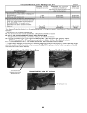
...Use) Parts & Accessories (if purchased) Accessories (e.g., grass catcher, bumper guard accessories, etc. 1 Year No Warranty No Warranty Parts (e.g., belts, blades, etc.) 90 days No Warranty No Warranty Parts & Accessories (if replaced in Warranty Service) Replacement parts and/or accessories provided...last date of the complete unit's final production, whichever comes first. RZ - Two (2) Year Consumer warranty, parts & labor, with Husqvarna. Deck Shell replacement will be limited to a maximum of the warranty statement. LCT Engines on Tiller tines and Fabricated Deck shell is...
...Use) Parts & Accessories (if purchased) Accessories (e.g., grass catcher, bumper guard accessories, etc. 1 Year No Warranty No Warranty Parts (e.g., belts, blades, etc.) 90 days No Warranty No Warranty Parts & Accessories (if replaced in Warranty Service) Replacement parts and/or accessories provided...last date of the complete unit's final production, whichever comes first. RZ - Two (2) Year Consumer warranty, parts & labor, with Husqvarna. Deck Shell replacement will be limited to a maximum of the warranty statement. LCT Engines on Tiller tines and Fabricated Deck shell is...
Parts Manual
Page 9
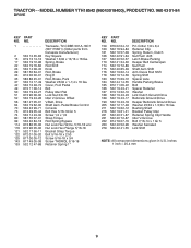
... 279 532 42 41-55 DESCRIPTION Pin Cotter 1/8 x 3/4 Retainer Clip Spring, Return, Clutch Nut Push .625 Latch Brake Parking Keeper Belt Centerspan Nut Push Shaft Asm Shift Arm Clevis Rod Shift Spring Shift Spacer Axle Handle Parking Brake Bolt Spacer Retainer Washer Link Clutch Ground Drive... Bellcrank Ground Drive Keeper Bellcrank Ground Drive Washer 25/32 x 1-5/8 x 16 Ga. MODEL NUMBER YTH18542 (96043018400), PRODUCT NO. 960 43 01-84 DRIVE KEY PART NO. Pedal Brake Control Console Bolt Hex 5/16-18 Gr. 5 Screw 1/4 x 1/2...
... 279 532 42 41-55 DESCRIPTION Pin Cotter 1/8 x 3/4 Retainer Clip Spring, Return, Clutch Nut Push .625 Latch Brake Parking Keeper Belt Centerspan Nut Push Shaft Asm Shift Arm Clevis Rod Shift Spring Shift Spacer Axle Handle Parking Brake Bolt Spacer Retainer Washer Link Clutch Ground Drive... Bellcrank Ground Drive Keeper Bellcrank Ground Drive Washer 25/32 x 1-5/8 x 16 Ga. MODEL NUMBER YTH18542 (96043018400), PRODUCT NO. 960 43 01-84 DRIVE KEY PART NO. Pedal Brake Control Console Bolt Hex 5/16-18 Gr. 5 Screw 1/4 x 1/2...
Parts Manual
Page 11
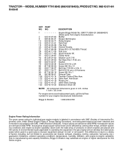
MODEL NUMBER YTH18542 (96043018400), PRODUCT NO. 960 43 01-84 ENGINE KEY PART NO. Torque values are derived at 3060 RPM; Actual gross engine power will not develop ... variability. DESCRIPTION 1 Engine Briggs Model No. 33R777-0004-G1 (585994001) (Order parts from engine manufacturer.) 2 532 44 67-60 Muffler 9 584 90 80-01 Keeper Belt Engine 12 532 40 54-71 Pulley Engine 15 532 41 41-51 Tank Fuel 18 532 43 92-08 Cap Fuel 20 532 40...
MODEL NUMBER YTH18542 (96043018400), PRODUCT NO. 960 43 01-84 ENGINE KEY PART NO. Torque values are derived at 3060 RPM; Actual gross engine power will not develop ... variability. DESCRIPTION 1 Engine Briggs Model No. 33R777-0004-G1 (585994001) (Order parts from engine manufacturer.) 2 532 44 67-60 Muffler 9 584 90 80-01 Keeper Belt Engine 12 532 40 54-71 Pulley Engine 15 532 41 41-51 Tank Fuel 18 532 43 92-08 Cap Fuel 20 532 40...
Parts Manual
Page 15
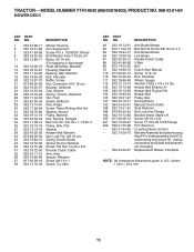
...Belt Pulley Idler Spring Return Manual Clutch Cable Stud Fastener Nut Lock Hex Flange Bracket Brake Stand LH Screw 3/8-16 x 3/4 Screw TT #10-32 5 3/8 Flange Port Washout Coupling Quick connect Mandrel Assembly (Includes housing (key #14), shaft assembly (key #13), and bearing only (key #15) - MODEL NUMBER YTH18542... Wsh Hd Washer, Spacer Pulley, Mandrel Nut, Toplock, Flanged Bolt Carr Sh. 3/8-16 x 1-1/2 Gr. 5 Pulley, Idler, Flat Washer Keeper Belt Mandrel Nut, Lock Flg. 3/8-16 unc Spring Torsion Brake Spring Torsion Retainer Screw Thd Roll 1/4-20 x 5/8 Bracket Clutch Cable Arm, Idler Spacer,...
...Belt Pulley Idler Spring Return Manual Clutch Cable Stud Fastener Nut Lock Hex Flange Bracket Brake Stand LH Screw 3/8-16 x 3/4 Screw TT #10-32 5 3/8 Flange Port Washout Coupling Quick connect Mandrel Assembly (Includes housing (key #14), shaft assembly (key #13), and bearing only (key #15) - MODEL NUMBER YTH18542... Wsh Hd Washer, Spacer Pulley, Mandrel Nut, Toplock, Flanged Bolt Carr Sh. 3/8-16 x 1-1/2 Gr. 5 Pulley, Idler, Flat Washer Keeper Belt Mandrel Nut, Lock Flg. 3/8-16 unc Spring Torsion Brake Spring Torsion Retainer Screw Thd Roll 1/4-20 x 5/8 Bracket Clutch Cable Arm, Idler Spacer,...
Parts Manual
Page 18
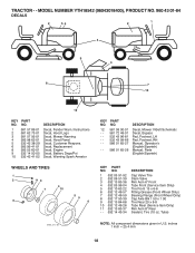
... 00-01 - - 581 72 48-01 - - 532 43 96-81 - - 532 43 99-66 - - 586 01 65-27 - - 586 01 65-26 DESCRIPTION Decal, Mower V-Belt Schematic Decal, Bypass Pad, Footrest, LH Pad, Footrest, RH Manual, Operator's (English/Spanish) Manual, Parts (English/Spanish) KEY PART NO. NO. 1 532 05 91-92... (Front Wheel Only) Cap Axle Blk 1 50 x 1 00 Tire Rear 20 x 8-8 Tube Rear (Service Item Only) Rim Asm 8" Rear Sealant, Tire (10 oz. MODEL NUMBER YTH18542 (96043018400), PRODUCT NO. 960 43 01-84 DECALS 2 56 2 1 4 9 3 8 7 10 12 KEY PART NO. NO. 1 581 57 89-01 2 581 62 73-01 3 581 57...
... 00-01 - - 581 72 48-01 - - 532 43 96-81 - - 532 43 99-66 - - 586 01 65-27 - - 586 01 65-26 DESCRIPTION Decal, Mower V-Belt Schematic Decal, Bypass Pad, Footrest, LH Pad, Footrest, RH Manual, Operator's (English/Spanish) Manual, Parts (English/Spanish) KEY PART NO. NO. 1 532 05 91-92... (Front Wheel Only) Cap Axle Blk 1 50 x 1 00 Tire Rear 20 x 8-8 Tube Rear (Service Item Only) Rim Asm 8" Rear Sealant, Tire (10 oz. MODEL NUMBER YTH18542 (96043018400), PRODUCT NO. 960 43 01-84 DECALS 2 56 2 1 4 9 3 8 7 10 12 KEY PART NO. NO. 1 581 57 89-01 2 581 62 73-01 3 581 57...


