
Parts Manual
Page 1
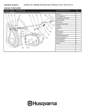
REPAIR PARTS MODEL NO. ST124 (97044930100), PRODUCT NO. 970 44 93 01 SNOW THROWER KIT PART NUMBER KIT DESCRIPTION 596139901 GEARBOX ASSY, 24 IN HOUSING 595920901 SERVICE KIT SHEAR PIN CONTENTS DESCRIPTION BOLT M6×20 BOLT M6×25 SPRING WASHER 6 WASHER 6 ANGLE HYDRAULIC GREASE NIPPLES M10×1 BALL BEARING 61904-2Z WASHER 20×27×1 BEARING 51104 OIL SEAL 20×32×5 WORM DEEP GROOVE BALL...
REPAIR PARTS MODEL NO. ST124 (97044930100), PRODUCT NO. 970 44 93 01 SNOW THROWER KIT PART NUMBER KIT DESCRIPTION 596139901 GEARBOX ASSY, 24 IN HOUSING 595920901 SERVICE KIT SHEAR PIN CONTENTS DESCRIPTION BOLT M6×20 BOLT M6×25 SPRING WASHER 6 WASHER 6 ANGLE HYDRAULIC GREASE NIPPLES M10×1 BALL BEARING 61904-2Z WASHER 20×27×1 BEARING 51104 OIL SEAL 20×32×5 WORM DEEP GROOVE BALL...

Parts Manual
Page 3
ST124 (97044930100), PRODUCT NO. 970 44 93 01 SNOW THROWER KIT PART NUMBER KIT DESCRIPTION 595921002 SERVICE KIT AUGER HARDWARE 24 IN CONTENTS DESCRIPTION COVER,SHAFT SHAFT BUSH FIXED BUSH ADJUSTING BUSH WASHER 19.5×34×1.5 BIG WASHER 8 BOLT M8×12 QTY 2 2 4 8 4 6 6 595921201 IMPELLER ASSY WELDMENT IMPELLER WELDMENT 1 REPAIR PARTS MODEL NO.
ST124 (97044930100), PRODUCT NO. 970 44 93 01 SNOW THROWER KIT PART NUMBER KIT DESCRIPTION 595921002 SERVICE KIT AUGER HARDWARE 24 IN CONTENTS DESCRIPTION COVER,SHAFT SHAFT BUSH FIXED BUSH ADJUSTING BUSH WASHER 19.5×34×1.5 BIG WASHER 8 BOLT M8×12 QTY 2 2 4 8 4 6 6 595921201 IMPELLER ASSY WELDMENT IMPELLER WELDMENT 1 REPAIR PARTS MODEL NO.

Parts Manual
Page 4
ST124 (97044930100), PRODUCT NO. 970 44 93 01 SNOW THROWER KIT PART NUMBER KIT DESCRIPTION 595924304 24 IN HOUSING WELDMENT KIT WITH DECALS CONTENTS DESCRIPTION 24 IN AUGER HOUSING FLAT WASHER 8 BOLT M8 DECAL (PR230) WARNING LABEL(108×78) QTY 1 6 6 1 1 595924401 CLEANOUT TOOL AND HARDWARE SCREW ST4.2×12 2 PRESS CAP 2 BRACKET, SHOVEL 1 SHOVEL 1 REPAIR PARTS MODEL NO.
ST124 (97044930100), PRODUCT NO. 970 44 93 01 SNOW THROWER KIT PART NUMBER KIT DESCRIPTION 595924304 24 IN HOUSING WELDMENT KIT WITH DECALS CONTENTS DESCRIPTION 24 IN AUGER HOUSING FLAT WASHER 8 BOLT M8 DECAL (PR230) WARNING LABEL(108×78) QTY 1 6 6 1 1 595924401 CLEANOUT TOOL AND HARDWARE SCREW ST4.2×12 2 PRESS CAP 2 BRACKET, SHOVEL 1 SHOVEL 1 REPAIR PARTS MODEL NO.

Parts Manual
Page 22
ST124 (97044930100), PRODUCT NO. 970 44 93 01 SNOW THROWER KIT PART NUMBER KIT DESCRIPTION 596018201 ENGINE KEY CONTENTS DESCRIPTION ENGINE KEY SET OF 2 QTY 1 596015902 RH WHEEL ASSEMBLY AND COMPONENTS TIRE 13×4.1-6 1 HUB 13×4.1-6 1 AIR VALVE 1 CAP AIR VALVE 1 SHAFT SLEEVE WITH HOLE, HUB 1 SHAFT SLEEVE WITHOUT HOLE, 1 HUB WASHER 19.5×34×1.5 1 REPAIR PARTS MODEL NO.
ST124 (97044930100), PRODUCT NO. 970 44 93 01 SNOW THROWER KIT PART NUMBER KIT DESCRIPTION 596018201 ENGINE KEY CONTENTS DESCRIPTION ENGINE KEY SET OF 2 QTY 1 596015902 RH WHEEL ASSEMBLY AND COMPONENTS TIRE 13×4.1-6 1 HUB 13×4.1-6 1 AIR VALVE 1 CAP AIR VALVE 1 SHAFT SLEEVE WITH HOLE, HUB 1 SHAFT SLEEVE WITHOUT HOLE, 1 HUB WASHER 19.5×34×1.5 1 REPAIR PARTS MODEL NO.
Parts Manual
Page 26
REPAIR PARTS MODEL NO. ST124 (97044930100), PRODUCT NO. 970 44 93 01 SNOW THROWER KIT PART NUMBER KIT DESCRIPTION 596017901 CHUTE ROTATOR HANDLE AND COMPONENTS CONTENTS DESCRIPTION CIRCLIP F FLAT WASHER 10 FIXED BOARD, ROTATOR SEAT,ROTATOR BOLT M8×20 FIXED ROD, ROTATOR NUT M8 WASHER 8 ROD BIG WASHER BOLT M6×12 HANDLE BAR ROTATOR LOCK NUT HANDLE BUSH ROTATOR FLAT WASHER 8 NUT M8 QTY 1 2 1 1 2 1 1 2 1 1 1 1 1 1 2 8
REPAIR PARTS MODEL NO. ST124 (97044930100), PRODUCT NO. 970 44 93 01 SNOW THROWER KIT PART NUMBER KIT DESCRIPTION 596017901 CHUTE ROTATOR HANDLE AND COMPONENTS CONTENTS DESCRIPTION CIRCLIP F FLAT WASHER 10 FIXED BOARD, ROTATOR SEAT,ROTATOR BOLT M8×20 FIXED ROD, ROTATOR NUT M8 WASHER 8 ROD BIG WASHER BOLT M6×12 HANDLE BAR ROTATOR LOCK NUT HANDLE BUSH ROTATOR FLAT WASHER 8 NUT M8 QTY 1 2 1 1 2 1 1 2 1 1 1 1 1 1 2 8

Owner Manual
Page 2
Chute rotator control 6. Augers 10. Skid plate 11. Lower handle 15. Auger cable 5. Chute deflector 7. Drive speed control rod 16. Drive speed control lever 3. Control panel 4. Auger housing 9 9. Contents Introduction 2 Safety 3 Assembly 6 Maintenance 14 Troubleshooting 17 Transportation, storage and disposal 19 Operation 9 Technical data 19 Introduction Product overview 19 18 16 15 14 13 12 11 1 2 3 4 5 17 6 20 21 22 23 7 8 24 10 1. Auger engagement 2. Oil fill 13. Tire 12. Engine 14. Clean-out tool 8. Drive cable 2 1272 - 003...
Chute rotator control 6. Augers 10. Skid plate 11. Lower handle 15. Auger cable 5. Chute deflector 7. Drive speed control rod 16. Drive speed control lever 3. Control panel 4. Auger housing 9 9. Contents Introduction 2 Safety 3 Assembly 6 Maintenance 14 Troubleshooting 17 Transportation, storage and disposal 19 Operation 9 Technical data 19 Introduction Product overview 19 18 16 15 14 13 12 11 1 2 3 4 5 17 6 20 21 22 23 7 8 24 10 1. Auger engagement 2. Oil fill 13. Tire 12. Engine 14. Clean-out tool 8. Drive cable 2 1272 - 003...

Owner Manual
Page 3
... fields, roads, walkways and driveways. Fuel switch 23. 17. Recoil start handle 18. Safety Safety definitions The definitions below give the level of severity for damages that are damaged, contact the distributor to persons. 1272 - 003 - 09.08.2019 3 Do not put any part of fire. Primer 21. Use the clean-out tool to remove snow, do not do it on the...
... fields, roads, walkways and driveways. Fuel switch 23. 17. Recoil start handle 18. Safety Safety definitions The definitions below give the level of severity for damages that are damaged, contact the distributor to persons. 1272 - 003 - 09.08.2019 3 Do not put any part of fire. Primer 21. Use the clean-out tool to remove snow, do not do it on the...

Owner Manual
Page 4
... do maintenance to medical implants. Stay alert for hidden hazards or traffic. • After striking a foreign object, stop the engine (motor), remove the wire from its initial specification. Obey the safety symbols and the safety instructions. Only use approved attachments and accessories. • Do not use the product if it is changed from the spark plug, disconnect the cord on or crossing gravel drives, walks...
... do maintenance to medical implants. Stay alert for hidden hazards or traffic. • After striking a foreign object, stop the engine (motor), remove the wire from its initial specification. Obey the safety symbols and the safety instructions. Only use approved attachments and accessories. • Do not use the product if it is changed from the spark plug, disconnect the cord on or crossing gravel drives, walks...

Owner Manual
Page 5
... personal protective equipment when you operate the product. This includes, at all moving parts. Noise for transporting the product in moving parts. • Use approved protective gloves, if necessary. Disconnect the spark plug wire and keep a firm hold on slippery surfaces. • Handle fuel with a plastic liner. never run the engine indoors, except when starting motors. • Adjust the auger housing height to clear gravel or...
... personal protective equipment when you operate the product. This includes, at all moving parts. Noise for transporting the product in moving parts. • Use approved protective gloves, if necessary. Disconnect the spark plug wire and keep a firm hold on slippery surfaces. • Handle fuel with a plastic liner. never run the engine indoors, except when starting motors. • Adjust the auger housing height to clear gravel or...
Owner Manual
Page 6
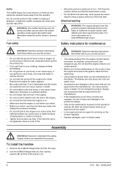
....ca.gov. Safety instructions for leaks regularly. • Be careful with fuel. If the fuel tank cap is not tightened, there is fuel or engine oil on the product regularly. • Replace damaged, worn or broken parts. Always use and when the engine operates at the top of the fuel tank. Remove the 4 M8x25 flange bolts (A) from the operator. Keep a space at idle speed. If you use the product if the...
....ca.gov. Safety instructions for leaks regularly. • Be careful with fuel. If the fuel tank cap is not tightened, there is fuel or engine oil on the product regularly. • Replace damaged, worn or broken parts. Always use and when the engine operates at the top of the fuel tank. Remove the 4 M8x25 flange bolts (A) from the operator. Keep a space at idle speed. If you use the product if the...
Owner Manual
Page 8
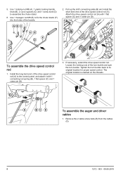
Use 1 locking nut M8 (A), 1 plastic locking handle knob (B), 2 curve spacers (C) and 1 screw level (D) to fix the chute rotator (F) into the holes of the drive speed control rod (A). ABC CE F D 2. Install the long bent end of the turn buckle and spin the turn buckle back to the control panel, and attach it with 1 flat spacer (C) and 1 cotter pin (D). C D A To assemble the drive speed control rod 1. If necessary, extend the drive speed control rod. Tighten the turn buckle. Remove the...
Use 1 locking nut M8 (A), 1 plastic locking handle knob (B), 2 curve spacers (C) and 1 screw level (D) to fix the chute rotator (F) into the holes of the drive speed control rod (A). ABC CE F D 2. Install the long bent end of the turn buckle and spin the turn buckle back to the control panel, and attach it with 1 flat spacer (C) and 1 cotter pin (D). C D A To assemble the drive speed control rod 1. If necessary, extend the drive speed control rod. Tighten the turn buckle. Remove the...

Owner Manual
Page 9
... the operation instructions. Connect and lock the left and the right cable thread insert (D) and the cable screw bolt (B) until the top of 10% ethanol (E10). Attach the 2 cable screw bolts (B) to be thrown is controlled by the chute rotator control which is aligned with a fuel can cause damage to set the rotating direction of fire. 5. See Maintenance schedule on page 14. • Make sure the ignition lead...
... the operation instructions. Connect and lock the left and the right cable thread insert (D) and the cable screw bolt (B) until the top of 10% ethanol (E10). Attach the 2 cable screw bolts (B) to be thrown is controlled by the chute rotator control which is aligned with a fuel can cause damage to set the rotating direction of fire. 5. See Maintenance schedule on page 14. • Make sure the ignition lead...
Owner Manual
Page 11
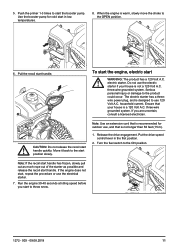
electric starter. The electric starter has a threewire power plug, and is warm, slowly move the choke to the OPEN position. 6. three-wire grounded system. Turn the fuel switch to the product could occur. Pull the recoil start the booster pump. Do not use 120 Volt A.C. Ensure that is not a 120 Volt A.C. If you start to start handle. Release the drive engagement. If the engine does not start in the first position. 2. Push the primer 1-3 times to...
electric starter. The electric starter has a threewire power plug, and is warm, slowly move the choke to the OPEN position. 6. three-wire grounded system. Turn the fuel switch to the product could occur. Pull the recoil start the booster pump. Do not use 120 Volt A.C. Ensure that is not a 120 Volt A.C. If you start to start handle. Release the drive engagement. If the engine does not start in the first position. 2. Push the primer 1-3 times to...

Owner Manual
Page 13
... drive wheels. 2. Move the drive speed control lever to the left to the OFF position. 3. Turn the fuel switch to operate the product forward. Pull out the on the location of the product to stop throwing snow. 2. Operate the drive engagement with the drive speed control lever. To get a good result • Always run the engine at full throttle or near full throttle. • Always adapt the speed of the drive speed control lever. 4. Release the drive engagement to the snow...
... drive wheels. 2. Move the drive speed control lever to the left to the OFF position. 3. Turn the fuel switch to operate the product forward. Pull out the on the location of the product to stop throwing snow. 2. Operate the drive engagement with the drive speed control lever. To get a good result • Always run the engine at full throttle or near full throttle. • Always adapt the speed of the drive speed control lever. 4. Release the drive engagement to the snow...

Owner Manual
Page 14
... oil drain plug. 1 Replace the oil after the first 20 h, 50 h, 100 h and then every 100 h. 2 See Technical data for correct tire pressure. 3 Check and clean spark plug before you start the product. 1. Remove the oil tank cap with the used engine oil. 2. Put the product on level ground. 2. Remove the ignition key. 5. Remove the dipstick. 6. WARNING: The engine oil is not necessary to add grease or to do damage to the edge of the oil level. 5. Replace...
... oil drain plug. 1 Replace the oil after the first 20 h, 50 h, 100 h and then every 100 h. 2 See Technical data for correct tire pressure. 3 Check and clean spark plug before you start the product. 1. Remove the oil tank cap with the used engine oil. 2. Put the product on level ground. 2. Remove the ignition key. 5. Remove the dipstick. 6. WARNING: The engine oil is not necessary to add grease or to do damage to the edge of the oil level. 5. Replace...
Owner Manual
Page 15
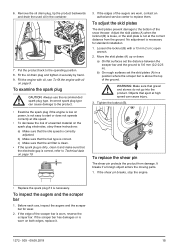
... the air filter is clean. • If the spark plug is dirty, clean it securely by hand. 9. A B To replace the shear pin The shear pin protects the product from the ground. Put the product back to Technical data on the spark plug electrodes, obey these instructions: a) Make sure that the fuel type is above the top of the snow thrower. To inspect the augers and the scraper bar 1. 6. Remove the oil drain plug, tip...
... the air filter is clean. • If the spark plug is dirty, clean it securely by hand. 9. A B To replace the shear pin The shear pin protects the product from the ground. Put the product back to Technical data on the spark plug electrodes, obey these instructions: a) Make sure that the fuel type is above the top of the snow thrower. To inspect the augers and the scraper bar 1. 6. Remove the oil drain plug, tip...
Owner Manual
Page 16
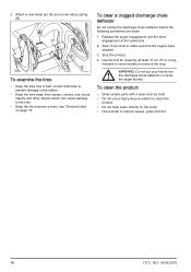
... chute deflector or inside the auger bucket. Use the tool for cleaning (at the same time. 2. Release the auger engagement and the drive engagement at least 37 cm (15 in.) long, included in some models) to make sure that the augers have stopped. 3. Wait 10 seconds to remove the clog. 2. Attach a new shear pin (A) and a new clamp spring (B). B A To examine the tires • Keep the tires free of fuel, oil...
... chute deflector or inside the auger bucket. Use the tool for cleaning (at the same time. 2. Release the auger engagement and the drive engagement at least 37 cm (15 in.) long, included in some models) to make sure that the augers have stopped. 3. Wait 10 seconds to remove the clog. 2. Attach a new shear pin (A) and a new clamp spring (B). B A To examine the tires • Keep the tires free of fuel, oil...

Owner Manual
Page 17
... the speed and the width of the fuel tank. The choke is blocked. The engine is not connected. The spark plug wire is flooded. There is in the fuel line. Decreased power Other causes. The throttle is vapor locked in STOP position. The spark plug wire is covered with ice or snow. The fuel tank cap is not connected. The muffler is cool. Solution Insert the safety ignition key. Fill the fuel tank with fresh, clean gasoline...
... the speed and the width of the fuel tank. The choke is blocked. The engine is not connected. The spark plug wire is flooded. There is in the fuel line. Decreased power Other causes. The throttle is vapor locked in STOP position. The spark plug wire is covered with ice or snow. The fuel tank cap is not connected. The muffler is cool. Solution Insert the safety ignition key. Fill the fuel tank with fresh, clean gasoline...

Owner Manual
Page 18
... start handle is The recoil start handle is stretched. Foreign objects clog the augers. The shear pin is not running. The lights are locked into position. Clean the fuel line. Tighten all fasteners. Replace the damaged parts. Check / replace the belt. Check / reinstall the belt. The fuel line is too old. Excessive snow and ice build up from the augers. If vibration remains, contact an authorized service center. If the engine does not start handle. Adjust the belt. Replace the broken shear pin. Replace...
... start handle is The recoil start handle is stretched. Foreign objects clog the augers. The shear pin is not running. The lights are locked into position. Clean the fuel line. Tighten all fasteners. Replace the damaged parts. Check / replace the belt. Check / reinstall the belt. The fuel line is too old. Excessive snow and ice build up from the augers. If vibration remains, contact an authorized service center. If the engine does not start handle. Adjust the belt. Replace the broken shear pin. Replace...

Owner Manual
Page 19
... location. • When the product is no leaks or fumes. Problem The chute rotator is difficult to move The product turns to one wheel. The tire pressure is debris in the chute rotator mechanism. Inspect the tire lock pin. Adjust the skid plates and the sledge. Technical data Technical data Product specifications Gasoline capacity and type Oil type (API SJ-SN) Oil capacity Spark plug Spark plug electrode gap Tire pressure 2.2 L (74 U.S. The cables...
... location. • When the product is no leaks or fumes. Problem The chute rotator is difficult to move The product turns to one wheel. The tire pressure is debris in the chute rotator mechanism. Inspect the tire lock pin. Adjust the skid plates and the sledge. Technical data Technical data Product specifications Gasoline capacity and type Oil type (API SJ-SN) Oil capacity Spark plug Spark plug electrode gap Tire pressure 2.2 L (74 U.S. The cables...


