

Installation Instructions
Page 1
... installing the deck on idler arms). Lower the deck to Operators Manual when needed. Remove deck belt shields. *Supplied in injury. a. Leave the deck lift in the transport position (furthest forward position). 4. Slide the deck under the deck. 11. Line up with the brackets on the deck. 8. Carriage bolt, 5/16-18 x 1 c. INSTALLATION INSTRUCTIONS PZ 60 inch Side Discharge Deck Kit - 966555302 Tools Required • ½" socket or wrench (battery terminals, strut shaft). • ½" breaker bar...
... installing the deck on idler arms). Lower the deck to Operators Manual when needed. Remove deck belt shields. *Supplied in injury. a. Leave the deck lift in the transport position (furthest forward position). 4. Slide the deck under the deck. 11. Line up with the brackets on the deck. 8. Carriage bolt, 5/16-18 x 1 c. INSTALLATION INSTRUCTIONS PZ 60 inch Side Discharge Deck Kit - 966555302 Tools Required • ½" socket or wrench (battery terminals, strut shaft). • ½" breaker bar...

Installation Instructions
Page 2
... With a ½" breaker bar, shift the idler arm counter clockwise. Correct if needed. 17. Adjust belt tension by turning the eyebolt until there is enough slack, slip the belt onto the center spindle pulley. Double check belt routing to 60-70 lbs. 19. INSTALLATION INSTRUCTIONS Deck Belt Installation NOTE: For ease in installing the deck belt, refer to the routing decal on both mandrel housings and secure with fasteners. Replace belt shields on the cutting deck. 13.
... With a ½" breaker bar, shift the idler arm counter clockwise. Correct if needed. 17. Adjust belt tension by turning the eyebolt until there is enough slack, slip the belt onto the center spindle pulley. Double check belt routing to 60-70 lbs. 19. INSTALLATION INSTRUCTIONS Deck Belt Installation NOTE: For ease in installing the deck belt, refer to the routing decal on both mandrel housings and secure with fasteners. Replace belt shields on the cutting deck. 13.

Installation Instructions
Page 3
... a level surface. check that measurement is the same. WARNING! Locknut a b 8065-037 Retain measurement. If tires are equal. If adjustment is required, loosen the locknut and adjust bolt up to -rear manner. Reposition rear mounting bolts up or down until both outer blades to align with a heavy cloth when handling. 22. a. NOTE: To insure accuracy of leveling procedure, mower deck drive belt must be equal in Maintenance...
... a level surface. check that measurement is the same. WARNING! Locknut a b 8065-037 Retain measurement. If tires are equal. If adjustment is required, loosen the locknut and adjust bolt up to -rear manner. Reposition rear mounting bolts up or down until both outer blades to align with a heavy cloth when handling. 22. a. NOTE: To insure accuracy of leveling procedure, mower deck drive belt must be equal in Maintenance...

Installation Instructions
Page 4
Reconnect negative cable to adjust the deck lift springs. Deck lift spring 8065-062 Loosen the nut and adjust the spring tension. 25. Access the springs by tilting the seat forward. 24. INSTALLATION INSTRUCTIONS Deck Lift Spring When mowing 2" or lower, it may be necessary to the battery when deck installation is complete.
Reconnect negative cable to adjust the deck lift springs. Deck lift spring 8065-062 Loosen the nut and adjust the spring tension. 25. Access the springs by tilting the seat forward. 24. INSTALLATION INSTRUCTIONS Deck Lift Spring When mowing 2" or lower, it may be necessary to the battery when deck installation is complete.

Installation Instructions
Page 5
... 2½" to 4" (63 to 102 mm) grass. • Lower position 4" to 5" (102 to 127 mm) grass. Do not adjust the rollers to help prevent scalping in most terrain conditions. IMPORTANT INFORMATION Adjust anti-scalp rollers with the mower on a flat level surface. INSTALLATION INSTRUCTIONS Anti-scalp Rollers Anti-scalp rollers keep the deck in the proper position to support the deck.
... 2½" to 4" (63 to 102 mm) grass. • Lower position 4" to 5" (102 to 127 mm) grass. Do not adjust the rollers to help prevent scalping in most terrain conditions. IMPORTANT INFORMATION Adjust anti-scalp rollers with the mower on a flat level surface. INSTALLATION INSTRUCTIONS Anti-scalp Rollers Anti-scalp rollers keep the deck in the proper position to support the deck.

Installation Instructions
Page 7
.......1..... DESCRIPTION 37.. 539 976978....4..... BELT, DECK Gasoline or Propane Models 522 860201....1..... BLADE, HIGH LIFT 21" 574 481301....3..... QTY. PULLEY 4.. 574 197002....1..... CHUTE, DISCHARGE 12.. 525 486002....1..... BOLT 3/8-16 x 4½ HEX GR 8 47.. 510 015101....1..... EYEBOLT 3/8 x 4 49.. 525 465601....1..... KEEPER, BELT 52.. 574 262102....1..... SHAFT, SPINDLE 56.. 539 130643....6..... DECAL, NO STEP 60.. 539 113224....1..... BRACKET, CHUTE SUPPORT 13.. 510 263701....3..... BOLT ½-13 x 4¾...
.......1..... DESCRIPTION 37.. 539 976978....4..... BELT, DECK Gasoline or Propane Models 522 860201....1..... BLADE, HIGH LIFT 21" 574 481301....3..... QTY. PULLEY 4.. 574 197002....1..... CHUTE, DISCHARGE 12.. 525 486002....1..... BOLT 3/8-16 x 4½ HEX GR 8 47.. 510 015101....1..... EYEBOLT 3/8 x 4 49.. 525 465601....1..... KEEPER, BELT 52.. 574 262102....1..... SHAFT, SPINDLE 56.. 539 130643....6..... DECAL, NO STEP 60.. 539 113224....1..... BRACKET, CHUTE SUPPORT 13.. 510 263701....3..... BOLT ½-13 x 4¾...

Installation Instructions
Page 8
...5 SAE Grade 8 Flangelock Screw w/Flangelock Nut ft./lbs ft./lbs Nm ft./lbs Nm ft./lbs Nm ¼ 9 12 13 18 Shank Size (Diameter in millimeters, fine or coarse thread) Minimum commercial quality (lower quality not recommended) Metric Standard Hardware Grade Grade 8.8 Grade 10.9 ft./lbs... 224 5/8 150 203 225 305 ¾ 250 339 370 502 7/8 378 513 591 801 11/8 782 1060 1410 1912 ** Grade 5 - INSTALLATION INSTRUCTIONS HEX HEAD CAP SCREWS The torque values shown should be used as a general guideline when specific torque values are not given. U.S.
...5 SAE Grade 8 Flangelock Screw w/Flangelock Nut ft./lbs ft./lbs Nm ft./lbs Nm ft./lbs Nm ¼ 9 12 13 18 Shank Size (Diameter in millimeters, fine or coarse thread) Minimum commercial quality (lower quality not recommended) Metric Standard Hardware Grade Grade 8.8 Grade 10.9 ft./lbs... 224 5/8 150 203 225 305 ¾ 250 339 370 502 7/8 378 513 591 801 11/8 782 1060 1410 1912 ** Grade 5 - INSTALLATION INSTRUCTIONS HEX HEAD CAP SCREWS The torque values shown should be used as a general guideline when specific torque values are not given. U.S.
Parts Manual
Page 2
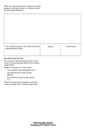
Transmission ©2016 All rights reserved. Orangeburg SC. Printed in service questions, warranty issues, etc., please consult the following professional: This manual belongs to the engine compartment. When you need spare parts or support in U.S.A. Stated on the printed plate affixed to the machine with the manufacturing number: Engine Manufacturing Number The machine's manufacturing number can be found on the plate, from the...
Transmission ©2016 All rights reserved. Orangeburg SC. Printed in service questions, warranty issues, etc., please consult the following professional: This manual belongs to the engine compartment. When you need spare parts or support in U.S.A. Stated on the printed plate affixed to the machine with the manufacturing number: Engine Manufacturing Number The machine's manufacturing number can be found on the plate, from the...
Parts Manual
Page 3
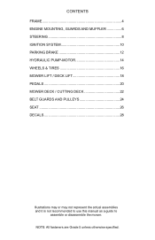
NOTE: All fasteners are Grade 5 unless otherwise specified. CONTENTS FRAME 4 ENGINE MOUNTING, GUARDS AND MUFFLER 6 STEERING 8 IGNITION SYSTEM 10 PARKING BRAKE 12 HYDRAULIC PUMP-MOTOR 14 WHEELS & TIRES 16 MOWER LIFT / DECK LIFT 18 PEDALS 20 MOWER DECK / CUTTING DECK 22 BELT GUARDS AND PULLEYS 24 SEAT 26 DECALS 28 Illustrations may or may not represent the actual assemblies and it is not recommended to use this manual as a guide to assemble or disassemble the mower.
NOTE: All fasteners are Grade 5 unless otherwise specified. CONTENTS FRAME 4 ENGINE MOUNTING, GUARDS AND MUFFLER 6 STEERING 8 IGNITION SYSTEM 10 PARKING BRAKE 12 HYDRAULIC PUMP-MOTOR 14 WHEELS & TIRES 16 MOWER LIFT / DECK LIFT 18 PEDALS 20 MOWER DECK / CUTTING DECK 22 BELT GUARDS AND PULLEYS 24 SEAT 26 DECALS 28 Illustrations may or may not represent the actual assemblies and it is not recommended to use this manual as a guide to assemble or disassemble the mower.
Parts Manual
Page 5
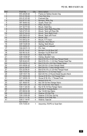
...27 28 29 30 31 32 33 34 35 36 37 38 39 40 41 PZ 60, 966 614301-04 Part No. 574 48 28-02 574 21 56-02 574 21 57-02 522... 1 Frame w/ Safety Decals Org 1 Floor Pan Org 1 Footrest Org 1 Bumper, Rear Org 1 Guard, Rear Gry 1 Plate, Skid Gry 1 Mount, Seat Org 1 Mount, Tank Right Rear Blk 1 Mount, Tank Left Rear Blk 1 Mount, Tank Right Front 1 Mount, Tank Left Front 4 Mount, ISO 4 Mount, F/F Insert 2 Bracket, Rest Mount 4 Spring, Tank Mount 2 Latch ... 4 Nut 1/4-20 Hex Nyloc 4 Washer 5/8 Std Flat 6 Washer 5/16 Disc Spring 4 Washer 5/16 SAE Flat 4 Washer, Special 1 Assembly, ROPS w/ Seat Belt 5
...27 28 29 30 31 32 33 34 35 36 37 38 39 40 41 PZ 60, 966 614301-04 Part No. 574 48 28-02 574 21 56-02 574 21 57-02 522... 1 Frame w/ Safety Decals Org 1 Floor Pan Org 1 Footrest Org 1 Bumper, Rear Org 1 Guard, Rear Gry 1 Plate, Skid Gry 1 Mount, Seat Org 1 Mount, Tank Right Rear Blk 1 Mount, Tank Left Rear Blk 1 Mount, Tank Right Front 1 Mount, Tank Left Front 4 Mount, ISO 4 Mount, F/F Insert 2 Bracket, Rest Mount 4 Spring, Tank Mount 2 Latch ... 4 Nut 1/4-20 Hex Nyloc 4 Washer 5/8 Std Flat 6 Washer 5/16 Disc Spring 4 Washer 5/16 SAE Flat 4 Washer, Special 1 Assembly, ROPS w/ Seat Belt 5

Parts Manual
Page 7
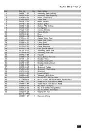
...Engine 510 01 98-01 1 Pulley, Engine 525 75 03-01 1 Muffler 525 74 95-01 1 Clutch, GT 3.5 522 67 67-02 1 Stop, Clutch 539 11 96-80 1 Adaptor, Oil Drain 539 11 89-11 2 Pipe 3/8 NPT x 3" 539 10 50-72 1 Elbow 90O 522 83 70-01 1 Plug 3/8 NPTF Drain 587 04 48-14 1 Fuel...Washer 7/16 Slotted Lock 539 10 25-93 4 Washer 3/8 Spring 539 12 56-26 1 Washer, Heavy NOT SHOWN 525 55 42-01 1 Engine Harness, Kaw 574 82 58-01 1 Kit, Spark Arrestor 586 83 97-01 2 Gasket, Exhaust 1 Engine, Kawasaki FX801V 25.5 Hp For Engine Replacement Parts, See a Kawasaki Dealer 7 Ref. 1 2 3 4 5...
...Engine 510 01 98-01 1 Pulley, Engine 525 75 03-01 1 Muffler 525 74 95-01 1 Clutch, GT 3.5 522 67 67-02 1 Stop, Clutch 539 11 96-80 1 Adaptor, Oil Drain 539 11 89-11 2 Pipe 3/8 NPT x 3" 539 10 50-72 1 Elbow 90O 522 83 70-01 1 Plug 3/8 NPTF Drain 587 04 48-14 1 Fuel...Washer 7/16 Slotted Lock 539 10 25-93 4 Washer 3/8 Spring 539 12 56-26 1 Washer, Heavy NOT SHOWN 525 55 42-01 1 Engine Harness, Kaw 574 82 58-01 1 Kit, Spark Arrestor 586 83 97-01 2 Gasket, Exhaust 1 Engine, Kawasaki FX801V 25.5 Hp For Engine Replacement Parts, See a Kawasaki Dealer 7 Ref. 1 2 3 4 5...

Parts Manual
Page 9
...39 40 41 42 43 44 45 46 47 48 49 50 51 PZ 60, 966 614301-04 Part No. 516 02 03-01 525 44 79-01 539 11 37...Assembly, Dampener 1 Assembly, Seat Strut 1 Switch, Brake (3-Pole) 2 Switch, Interlock 4 Bearing, Flange 2 Bracket, Control 2 Bracket, Dampener 2 Lever, Motion 1 Lever W/ Grip Right 1 Lever W/ Grip Left 2 Lever, Control 4 Turnbuckle 4 Ball End 1 Spring 1 Spring 1 Spring 2 Spacer, Pivot 1 Bushing 1/4 Flange 1 Link, Switch 2 Ball Stud 10Mm 2 Grip, Lever 2 Bumper 1 Knob 2 Linkage. Control Front 2 Linkage, Control Rear 2 Block, Tracking 1 Plate, Nut 4 Hairpin Cotter 4 Retainer, U Type 1 Bolt...
...39 40 41 42 43 44 45 46 47 48 49 50 51 PZ 60, 966 614301-04 Part No. 516 02 03-01 525 44 79-01 539 11 37...Assembly, Dampener 1 Assembly, Seat Strut 1 Switch, Brake (3-Pole) 2 Switch, Interlock 4 Bearing, Flange 2 Bracket, Control 2 Bracket, Dampener 2 Lever, Motion 1 Lever W/ Grip Right 1 Lever W/ Grip Left 2 Lever, Control 4 Turnbuckle 4 Ball End 1 Spring 1 Spring 1 Spring 2 Spacer, Pivot 1 Bushing 1/4 Flange 1 Link, Switch 2 Ball Stud 10Mm 2 Grip, Lever 2 Bumper 1 Knob 2 Linkage. Control Front 2 Linkage, Control Rear 2 Block, Tracking 1 Plate, Nut 4 Hairpin Cotter 4 Retainer, U Type 1 Bolt...
Parts Manual
Page 11
..., Seat 586 16 18-01 1 Meter, Service 574 45 54-01 1 Switch, Ignition 582 10 76-02 1 Switch, PTO 10 Amp 574 45 55-01 1 Key, Ignition 574 20 70-01 1 Control, Throttle 574 20 69-01 1 Cable, Choke 539 13 26-24 1 Knob 539 10 24-36 1 Battery 575 01 81-01 2 Cap w/ Tether, Fuel 576 61 81-01 2 Valve, Fuel Check 525 86 54-01 2 Fitting, Fuel 522...
..., Seat 586 16 18-01 1 Meter, Service 574 45 54-01 1 Switch, Ignition 582 10 76-02 1 Switch, PTO 10 Amp 574 45 55-01 1 Key, Ignition 574 20 70-01 1 Control, Throttle 574 20 69-01 1 Cable, Choke 539 13 26-24 1 Knob 539 10 24-36 1 Battery 575 01 81-01 2 Cap w/ Tether, Fuel 576 61 81-01 2 Valve, Fuel Check 525 86 54-01 2 Fitting, Fuel 522...
Parts Manual
Page 15
... 539 99 00-52 819 18 22-12 Qty Description 1 Frame, Sub Blk 1 Belt 1 Assembly, Oil Tank 1 Filter, 25 Micron 1 Pump, 16CC Right 1 Pump, 16CC Left 2 Pulley, Pump 17 mm 1 Pulley, Idler 1 Pivot, Idler 1 Pivot, Bearing 1 Arm, Idler w/ Bearings 1 Tube, Anti-Splash 1 Shield, Dust 1 Shield, Dust 2 Shield, Pulley 1 Spring, Pump 2 Assembly, Vibration 1 Elbow 90 Degree 2 Connector 4 Connector, Straight 7 Connector, Straight 1 Line, Hydraulic, Right-A 1 Line...
... 539 99 00-52 819 18 22-12 Qty Description 1 Frame, Sub Blk 1 Belt 1 Assembly, Oil Tank 1 Filter, 25 Micron 1 Pump, 16CC Right 1 Pump, 16CC Left 2 Pulley, Pump 17 mm 1 Pulley, Idler 1 Pivot, Idler 1 Pivot, Bearing 1 Arm, Idler w/ Bearings 1 Tube, Anti-Splash 1 Shield, Dust 1 Shield, Dust 2 Shield, Pulley 1 Spring, Pump 2 Assembly, Vibration 1 Elbow 90 Degree 2 Connector 4 Connector, Straight 7 Connector, Straight 1 Line, Hydraulic, Right-A 1 Line...

Parts Manual
Page 19
...35 36 37 38 39 40 41 42 43 44 45 PZ 60, 966 614301-04 Part No. 510 40 85-02 510 40 86-02 525 ...Rod, Lift 2 Shaft, Lift Rear 1 Shaft, Lift Front 3 Trunion, Lift Shaft 3 Assembly, Deck Lift 2 Pivot, Spring 1 Latch, Transport 4 Bushing, Flanged 2 Bushing, Sleeve 3/4 x 1 2 Spring, Extension 1 Spring, Torsion 2 Assembly, Strut 1 Swivel 3/4 Balljoint 4 Spacer, Strut 1 Spacer, Height Plate 3 Arm, Lift 1 Arm, Cast Lift 3 Lift Chain 1 Guide, Height Bar 6 Pin 7/16 Clevis 1 Pin, Height 2 Pin, Strut 2 Eyebolt 4-1/2 4 Key 5/16 Square x 1 2 E-Ring 5/8 4 E-Ring 7/16 6 E-Ring 3/4 2 Plate, Pillow Block 1 Bolt...
...35 36 37 38 39 40 41 42 43 44 45 PZ 60, 966 614301-04 Part No. 510 40 85-02 510 40 86-02 525 ...Rod, Lift 2 Shaft, Lift Rear 1 Shaft, Lift Front 3 Trunion, Lift Shaft 3 Assembly, Deck Lift 2 Pivot, Spring 1 Latch, Transport 4 Bushing, Flanged 2 Bushing, Sleeve 3/4 x 1 2 Spring, Extension 1 Spring, Torsion 2 Assembly, Strut 1 Swivel 3/4 Balljoint 4 Spacer, Strut 1 Spacer, Height Plate 3 Arm, Lift 1 Arm, Cast Lift 3 Lift Chain 1 Guide, Height Bar 6 Pin 7/16 Clevis 1 Pin, Height 2 Pin, Strut 2 Eyebolt 4-1/2 4 Key 5/16 Square x 1 2 E-Ring 5/8 4 E-Ring 7/16 6 E-Ring 3/4 2 Plate, Pillow Block 1 Bolt...

Parts Manual
Page 21
...20 21 22 23 24 25 26 27 28 29 30 31 32 33 34 PZ 60, 966 614301-04 Part No. 510 08 98-01 525 46 55-01 510 40 63-01 510...Rod, Lift 3 Assembly, Deck Lift 1 Bar, Height 1 Latch, Height 1 Bushing, Sleeve 3/4 x 1 1 Bushing 1 Spring, Torsion 1 Link, Indicator 1 Swivel, Height Latch 1 Swivel, Height Bar 1 Lever, Deck Lift 1 Pad, Foot Pedal 1 Pedal, Deck Height 1 Release, Pedal 1 Cap, Height Bar 1 Trunion, Lift Shaft 1 Arm, Lift 1 Lift Chain 2 Pin 7/16 Clevis 1 Rod, Height Latch 1 E-Ring 1 2 E-Ring 1/2 2 E-Ring 5/8 2 E-Ring 3/4 1 E-Ring 3/8 1 Bolt 5/16-18 x 1-1/2 Hex Flange Head 1 Bolt, Shoulder 1 Bolt...
...20 21 22 23 24 25 26 27 28 29 30 31 32 33 34 PZ 60, 966 614301-04 Part No. 510 08 98-01 525 46 55-01 510 40 63-01 510...Rod, Lift 3 Assembly, Deck Lift 1 Bar, Height 1 Latch, Height 1 Bushing, Sleeve 3/4 x 1 1 Bushing 1 Spring, Torsion 1 Link, Indicator 1 Swivel, Height Latch 1 Swivel, Height Bar 1 Lever, Deck Lift 1 Pad, Foot Pedal 1 Pedal, Deck Height 1 Release, Pedal 1 Cap, Height Bar 1 Trunion, Lift Shaft 1 Arm, Lift 1 Lift Chain 2 Pin 7/16 Clevis 1 Rod, Height Latch 1 E-Ring 1 2 E-Ring 1/2 2 E-Ring 5/8 2 E-Ring 3/4 1 E-Ring 3/8 1 Bolt 5/16-18 x 1-1/2 Hex Flange Head 1 Bolt, Shoulder 1 Bolt...
Parts Manual
Page 23
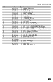
...02 1 Deck w/ Safety Decals 539 10 57-11 3 Blade, 21" 510 43 75-02 1 Baffle, Flow Diverter 574 19 70-02 1 Bracket, Chute Pivot 525 48 58-01 1 Chute, Discharge 525 48 60-02 1 Support, Chute Bracket 574 ...Type 539 11 90-07 3 Bolt, Blade 539 11 56-20 4 Bolt 1/4-20 x 3/4 Carriage 525 61 28-01 2 Bolt 3/8-16 x 1 Hex Flange Head 872 14 08-64 1 Bolt 1/2-13 x 8 Round Head Square Neck 510 02 23-01 2 Bolt... Lock NOT SHOWN 522 82 93-01 3 Blade, High Lift 21" 574 48 13-01 3 Blade, Low Lift 21" 522 93 66-01 3 Blade, Gator 21" 539 10 97-55 3 Blade, Wavy Rev Lift 21" 23 Ref. 1...
...02 1 Deck w/ Safety Decals 539 10 57-11 3 Blade, 21" 510 43 75-02 1 Baffle, Flow Diverter 574 19 70-02 1 Bracket, Chute Pivot 525 48 58-01 1 Chute, Discharge 525 48 60-02 1 Support, Chute Bracket 574 ...Type 539 11 90-07 3 Bolt, Blade 539 11 56-20 4 Bolt 1/4-20 x 3/4 Carriage 525 61 28-01 2 Bolt 3/8-16 x 1 Hex Flange Head 872 14 08-64 1 Bolt 1/2-13 x 8 Round Head Square Neck 510 02 23-01 2 Bolt... Lock NOT SHOWN 522 82 93-01 3 Blade, High Lift 21" 574 48 13-01 3 Blade, Low Lift 21" 522 93 66-01 3 Blade, Gator 21" 539 10 97-55 3 Blade, Wavy Rev Lift 21" 23 Ref. 1...

Parts Manual
Page 25
...-26 3 Valve, Grease Poppet 574 21 06-01 18 Bolt 1/2-13 X 1 Hex Flange Head 539 13 06-53 3 Nut 3/4-16 Hex Flange 580 94 33-04 3 Assembly, Spindle NOT SHOWN - OPTIONAL 574 75 42-01 1 Kit, Bearing Assembly When replacing the Spindle bearings, order the Bearing Assembly Kit to assure proper installation 25 Ref. 1 2 3 4 5 6 7 8 9 10 11 12 PZ 60, 966 614301-04 Part No.
...-26 3 Valve, Grease Poppet 574 21 06-01 18 Bolt 1/2-13 X 1 Hex Flange Head 539 13 06-53 3 Nut 3/4-16 Hex Flange 580 94 33-04 3 Assembly, Spindle NOT SHOWN - OPTIONAL 574 75 42-01 1 Kit, Bearing Assembly When replacing the Spindle bearings, order the Bearing Assembly Kit to assure proper installation 25 Ref. 1 2 3 4 5 6 7 8 9 10 11 12 PZ 60, 966 614301-04 Part No.

Parts Manual
Page 27
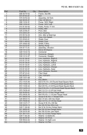
...10 11 12 13 14 15 16 17 18 19 20 21 22 23 24 25 26 PZ 60, 966 614301-04 Part No. 588 26 48-01 539 13 06-46 525 59 82-01 510 01 96-...Description 1 Belt 3 Pulley 1 Pulley, Idler 7" Narrow 1 Puller, Idler 6" Narrow 1 Pulley, Idler 7" 3 Shield, Dust 1 Shield, Dust 1 Arm, Idler w/ Spacer, Bearings 1 Spacer, Idler Pivot 1 Spring, Torsion, Idler 3 Bearing, Idler Arm 1 Bearing, Idler Pivot 2 Guard, Belt 1 Belt Guide, Blk 1 Belt Keeper 1 Eyebolt 3/8 x 4 1 Bolt 3/8-16 x 4-1/2 Hex Head Grade 8 2 Bolt 3/8-16 x 2-3/4 Hex Flange Head 9 Bolt 5/16-18 x 1/2 Hex Head 1 Bolt 3/8-16 x 2-1/2 Carriage 1 Bolt 5/16-...
...10 11 12 13 14 15 16 17 18 19 20 21 22 23 24 25 26 PZ 60, 966 614301-04 Part No. 588 26 48-01 539 13 06-46 525 59 82-01 510 01 96-...Description 1 Belt 3 Pulley 1 Pulley, Idler 7" Narrow 1 Puller, Idler 6" Narrow 1 Pulley, Idler 7" 3 Shield, Dust 1 Shield, Dust 1 Arm, Idler w/ Spacer, Bearings 1 Spacer, Idler Pivot 1 Spring, Torsion, Idler 3 Bearing, Idler Arm 1 Bearing, Idler Pivot 2 Guard, Belt 1 Belt Guide, Blk 1 Belt Keeper 1 Eyebolt 3/8 x 4 1 Bolt 3/8-16 x 4-1/2 Hex Head Grade 8 2 Bolt 3/8-16 x 2-3/4 Hex Flange Head 9 Bolt 5/16-18 x 1/2 Hex Head 1 Bolt 3/8-16 x 2-1/2 Carriage 1 Bolt 5/16-...

Parts Manual
Page 31
...10 11 12 13 14 15 16 17 18 19 20 21 22 23 24 25 PZ 60, 966 614301-04 Part No. 574 43 73-01 539 10 57-44 539 10 57-45 581 72 ...Belt Route 1 Decal, Belt Drive Warning 1 Decal, Battery Warning 2 Decal, No Step 1 Decal, Severing 2 Decal, Motion Control 1 Decal, Blade Warning 1 Decal, Deflector 2 Decal, Tracking 1 Decal, Park Brake 1 Decal, Warning 1 Decal, Crown H Small 2 Decal, Husqvarna 1 Decal, Fuse 1 Decal, ROPS 1 Decal, ROPS Warning 1 Decal, Crown Large 1 Decal, Service 1 Decal, Spark Arrestor 1 Decal, Height 1 Decal, Height 1 Decal, Console 1 Decal, PZ60 1 Decal, Fuel 1 Decal, Synthetic Oil...
...10 11 12 13 14 15 16 17 18 19 20 21 22 23 24 25 PZ 60, 966 614301-04 Part No. 574 43 73-01 539 10 57-44 539 10 57-45 581 72 ...Belt Route 1 Decal, Belt Drive Warning 1 Decal, Battery Warning 2 Decal, No Step 1 Decal, Severing 2 Decal, Motion Control 1 Decal, Blade Warning 1 Decal, Deflector 2 Decal, Tracking 1 Decal, Park Brake 1 Decal, Warning 1 Decal, Crown H Small 2 Decal, Husqvarna 1 Decal, Fuse 1 Decal, ROPS 1 Decal, ROPS Warning 1 Decal, Crown Large 1 Decal, Service 1 Decal, Spark Arrestor 1 Decal, Height 1 Decal, Height 1 Decal, Console 1 Decal, PZ60 1 Decal, Fuel 1 Decal, Synthetic Oil...


