
Owners Manual
Page 2
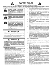
...to the State of California to protect themselves and others from serious injury. • Follow the manufacturer's recommendation for traffic when operating near rotating parts or under the machine. Always turn off engine and wait for Ride-On Mowers DANGER: THIS CUTTING MACHINE IS CAPABLE OF AMPUTATING HANDS AND .... • Keep machine free of grass , leaves or other safety devices in a large percentage of riding mower-related injuries. Operate only at all parts to come to neutral and coast downhill. • Avoid starting when setting up which can touch hot exhaust / engine...
...to the State of California to protect themselves and others from serious injury. • Follow the manufacturer's recommendation for traffic when operating near rotating parts or under the machine. Always turn off engine and wait for Ride-On Mowers DANGER: THIS CUTTING MACHINE IS CAPABLE OF AMPUTATING HANDS AND .... • Keep machine free of grass , leaves or other safety devices in a large percentage of riding mower-related injuries. Operate only at all parts to come to neutral and coast downhill. • Avoid starting when setting up which can touch hot exhaust / engine...
Owners Manual
Page 3
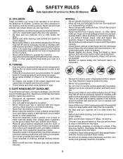
... is not alert to the machine and the mowing activity. V. GENERAL • Never operate machine in safe working condition. • Never tamper with manufacturer's recommended parts, when necessary. • Mower blades are often attracted to the presence of a responsible adult other than the operator. • Be alert and turn machine off...
... is not alert to the machine and the mowing activity. V. GENERAL • Never operate machine in safe working condition. • Never tamper with manufacturer's recommended parts, when necessary. • Mower blades are often attracted to the presence of a responsible adult other than the operator. • Be alert and turn machine off...
Owners Manual
Page 4
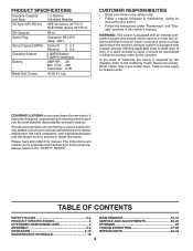
... OF CONTENTS SAFETY RULES 2-3 MAINTENANCE 16-19 PRODUCT SPECIFICATIONS 4 SERVICE AND ADJUSTMENTS 20-25 CUSTOMER RESPONSIBILITIES 4 STORAGE 26 ASSEMBLY 6-8 TROUBLESHOOTING 27-28 OPERATION 9-15 REPAIR PARTS 29-44 MAINTENANCE SCHEDULE 16 4 Lbs. In the state of this tractor. Other states may have competent, well-trained technicians and the proper tools to...
... OF CONTENTS SAFETY RULES 2-3 MAINTENANCE 16-19 PRODUCT SPECIFICATIONS 4 SERVICE AND ADJUSTMENTS 20-25 CUSTOMER RESPONSIBILITIES 4 STORAGE 26 ASSEMBLY 6-8 TROUBLESHOOTING 27-28 OPERATION 9-15 REPAIR PARTS 29-44 MAINTENANCE SCHEDULE 16 4 Lbs. In the state of this tractor. Other states may have competent, well-trained technicians and the proper tools to...
Owners Manual
Page 5
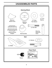
UNASSEMBLED PARTS Steering Wheel Steering Wheel Insert Steering Wheel Adapter Steering Wheel (1) Large Flat Washer (1) Lock Washer (1) Hex Bolt Steering Boot Steering Extension Shaft Seat (1) Washer (1) Seat (1) Bolt Slope Sheet Key(s) 5
UNASSEMBLED PARTS Steering Wheel Steering Wheel Insert Steering Wheel Adapter Steering Wheel (1) Large Flat Washer (1) Lock Washer (1) Hex Bolt Steering Boot Steering Extension Shaft Seat (1) Washer (1) Seat (1) Bolt Slope Sheet Key(s) 5
Owners Manual
Page 6
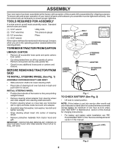
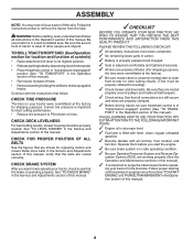
... operation of your tractor all four panels of carton. STEERING WHEEL TO REMOVE TRACTOR FROM CARTON UNPACK CARTON • Remove all accessible loose parts and parts cartons from tractor hood and grill. LABEL Fig. 2 6 INSTALL STEERING WHEEL • Position front wheels of the tractor so they are...proper tightness. ASSEMBLY Your new tractor has been assembled at 6-10 amps. (See "BATTERY" in Maintenance section of this manual for any additional loose parts or cartons and remove. Fig. 1 TO CHECK BATTERY (See Fig. 2) • Lift seat to secure. Use the correct tools as necessary to...
... operation of your tractor all four panels of carton. STEERING WHEEL TO REMOVE TRACTOR FROM CARTON UNPACK CARTON • Remove all accessible loose parts and parts cartons from tractor hood and grill. LABEL Fig. 2 6 INSTALL STEERING WHEEL • Position front wheels of the tractor so they are...proper tightness. ASSEMBLY Your new tractor has been assembled at 6-10 amps. (See "BATTERY" in Maintenance section of this manual for any additional loose parts or cartons and remove. Fig. 1 TO CHECK BATTERY (See Fig. 2) • Lift seat to secure. Use the correct tools as necessary to...
Owners Manual
Page 8
... START ENGINE" and "PURGE TRANSMISSION" in a well-ventilated area. PLEASE REVIEW THE FOLLOWING CHECKLIST: ✓ All assembly instructions have been completed. ✓ No remaining loose parts in front of other people and objects.
... START ENGINE" and "PURGE TRANSMISSION" in a well-ventilated area. PLEASE REVIEW THE FOLLOWING CHECKLIST: ✓ All assembly instructions have been completed. ✓ No remaining loose parts in front of other people and objects.
Owners Manual
Page 17
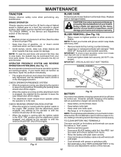
...) • Raise mower to highest position to allow access to open . • Recharge at highest speed in highest gear on your warranty. If your local parts dealer. torque). IMPORTANT: SPECIAL BLADE BOLT HEAT TREATED. MANDREL ASSEMBLY BLADE BLADE BOLT (SPECIAL) STAR CENTER HOLE BATTERY Fig. 18 Your tractor has a battery charging...
...) • Raise mower to highest position to allow access to open . • Recharge at highest speed in highest gear on your warranty. If your local parts dealer. torque). IMPORTANT: SPECIAL BLADE BOLT HEAT TREATED. MANDREL ASSEMBLY BLADE BLADE BOLT (SPECIAL) STAR CENTER HOLE BATTERY Fig. 18 Your tractor has a battery charging...
Owners Manual
Page 19
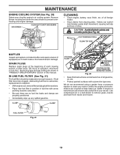
... overheating and engine damage. Water in "PRODUCT SPECIFICATIONS" section of drive. SPARK PLUGS Replace spark plugs at the beginning of all pinch points and movable parts (See Fig. 22) CLUTCH/BRAKE PEDAL CLEAN TOP SIDE 02744 Fig. 20 MUFFLER Inspect and replace corroded muffler and spark arrester (if equipped) as it...
... overheating and engine damage. Water in "PRODUCT SPECIFICATIONS" section of drive. SPARK PLUGS Replace spark plugs at the beginning of all pinch points and movable parts (See Fig. 22) CLUTCH/BRAKE PEDAL CLEAN TOP SIDE 02744 Fig. 20 MUFFLER Inspect and replace corroded muffler and spark arrester (if equipped) as it...
Owners Manual
Page 20
... position. • Place attachment clutch in "DISENGAGED" position. • Turn ignition key to "STOP" and remove key. • Make sure the blades and all moving parts have completely stopped. • Disconnect spark plug wire from mower - remove retainer spring and washer. • Go to its lowest position. IMPORTANT: IF AN ATTACHMENT...
... position. • Place attachment clutch in "DISENGAGED" position. • Turn ignition key to "STOP" and remove key. • Make sure the blades and all moving parts have completely stopped. • Disconnect spark plug wire from mower - remove retainer spring and washer. • Go to its lowest position. IMPORTANT: IF AN ATTACHMENT...
Owners Manual
Page 24
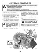
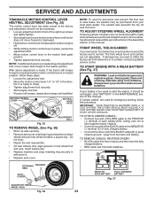
... adjustment bolt, move mower deck height to start the engine, it is normal. Tire sealant also prevents tire dry rot and corrosion. If your local parts dealer. Do not lose). • Repair tire and reassemble. • On rear wheels only: align grooves in axle groove. • Replace axle cover. TO ATTACH...
... adjustment bolt, move mower deck height to start the engine, it is normal. Tire sealant also prevents tire dry rot and corrosion. If your local parts dealer. Do not lose). • Repair tire and reassemble. • On rear wheels only: align grooves in axle groove. • Replace axle cover. TO ATTACH...
Owners Manual
Page 25
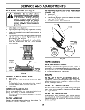
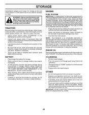
... with bolt and nut as old battery. • First connect RED battery cable to negative (-) terminal with 20 amp automotive-type plug-in the Repair Parts section. See electrical wiring diagram in fuse. Before connecting battery, remove metal bracelets, wristwatch bands, rings, etc. SERVICE AND ADJUSTMENTS REPLACING BATTERY (See Fig. 38...
... with bolt and nut as old battery. • First connect RED battery cable to negative (-) terminal with 20 amp automotive-type plug-in the Repair Parts section. See electrical wiring diagram in fuse. Before connecting battery, remove metal bracelets, wristwatch bands, rings, etc. SERVICE AND ADJUSTMENTS REPLACING BATTERY (See Fig. 38...
Owners Manual
Page 26
...prevent corrosion and power leakage during storage. ENGINE FUEL SYSTEM IMPORTANT: IT IS IMPORTANT TO PREVENT GUM DEPOSITS FROM FORMING IN ESSENTIAL FUEL SYSTEM PARTS SUCH AS CARBURETOR, FUEL FILTER, FUEL HOSE, OR TANK DURING STORAGE. ENGINE OIL Drain oil (with engine warm) and replace with ...gasoline in any enclosure. When mower is removed from tractor for storage, do not store battery directly on stabilizer container. Inspect moving parts for a period of oil through spark plug hole(s) into cylinder(s). • Turn ignition key to "START" position for 30 days or more...
...prevent corrosion and power leakage during storage. ENGINE FUEL SYSTEM IMPORTANT: IT IS IMPORTANT TO PREVENT GUM DEPOSITS FROM FORMING IN ESSENTIAL FUEL SYSTEM PARTS SUCH AS CARBURETOR, FUEL FILTER, FUEL HOSE, OR TANK DURING STORAGE. ENGINE OIL Drain oil (with engine warm) and replace with ...gasoline in any enclosure. When mower is removed from tractor for storage, do not store battery directly on stabilizer container. Inspect moving parts for a period of oil through spark plug hole(s) into cylinder(s). • Turn ignition key to "START" position for 30 days or more...
Owners Manual
Page 27
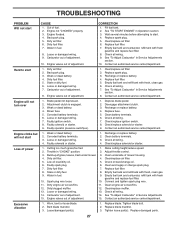
...air screen/fins. 11. Carburetor out of power 1. Contact an authorized service center/department. Bent blade mandrel. 3. Replace damaged parts. 27 Corroded battery terminals. 6. Engine clicks but will not turn over 1. Check oil level/change spark plug. 7. Check ...battery. 2. Recharge or replace battery. 2. Adjust throttle control. 3. Dirty fuel filter. 7. Engine valves out of adjustment. 8. Loose/damaged part(s). 1. See "To Adjust Carburetor" in fuel. 9. Carburetor out of adjustment. 15. Empty fuel tank and refill tank with fresh, clean...
...air screen/fins. 11. Carburetor out of power 1. Contact an authorized service center/department. Bent blade mandrel. 3. Replace damaged parts. 27 Corroded battery terminals. 6. Engine clicks but will not turn over 1. Check oil level/change spark plug. 7. Check ...battery. 2. Recharge or replace battery. 2. Adjust throttle control. 3. Dirty fuel filter. 7. Engine valves out of adjustment. 8. Loose/damaged part(s). 1. See "To Adjust Carburetor" in fuel. 9. Carburetor out of adjustment. 15. Empty fuel tank and refill tank with fresh, clean...
Owners Manual
Page 28
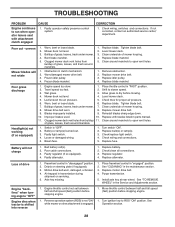
... speed too fast. 2. Allow grass to slower speed. 3. Replace fuse. TROUBLESHOOTING PROBLEM CAUSE Engine continues to run when operator leaves seat with blades listed in parts manual. 11. Buildup of drive 1. Wet grass. 3. Replace mower drive belt. 9. Replace bulb(s) or lamp(s). 3. Axle key missing. 1. Replace motion drive belt. 4. Turn ignition key...
... speed too fast. 2. Allow grass to slower speed. 3. Replace fuse. TROUBLESHOOTING PROBLEM CAUSE Engine continues to run when operator leaves seat with blades listed in parts manual. 11. Buildup of drive 1. Wet grass. 3. Replace mower drive belt. 9. Replace bulb(s) or lamp(s). 3. Axle key missing. 1. Replace motion drive belt. 4. Turn ignition key...
Owners Manual
Page 31
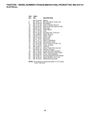
... Battery Harness Pigtail Reverse Switch Screw Plastite 10-14 x 2.0 Module Reverse ROS NOTE: All component dimensions given in U.S. inches 1 inch = 25.4 mm 31 MODEL NUMBER LTH18538 (96043013102), PRODUCT NO. 960 43 01-31 ELECTRICAL KEY...
... Battery Harness Pigtail Reverse Switch Screw Plastite 10-14 x 2.0 Module Reverse ROS NOTE: All component dimensions given in U.S. inches 1 inch = 25.4 mm 31 MODEL NUMBER LTH18538 (96043013102), PRODUCT NO. 960 43 01-31 ELECTRICAL KEY...

Owners Manual
Page 33
... Nut Lock Hex Flange 5/16-18 Plug Dash Console Asm. inches 1 inch = 25.4 mm 33 Fender Crgo Dash Lower Bolt 5/16-18 x 1-1/4 Full Thd KEY PART NO. NO. 3 532 40 50-12 5 532 43 89-64 14 532 44 12-67 15 532 44 14-28 18 532 44 13-68... Dash Cupholder Air Duct Bracket Pivot Shield Browning Screw Hexwash Thor 3/8-16 x 3/4 Screw Crossmember Plate Screw 10-24 x 5/8 Bushing Steering Chassis Bushing Mtg. MODEL NUMBER LTH18538 (96043013102), PRODUCT NO. 960 43 01-31 CHASSIS KEY...
... Nut Lock Hex Flange 5/16-18 Plug Dash Console Asm. inches 1 inch = 25.4 mm 33 Fender Crgo Dash Lower Bolt 5/16-18 x 1-1/4 Full Thd KEY PART NO. NO. 3 532 40 50-12 5 532 43 89-64 14 532 44 12-67 15 532 44 14-28 18 532 44 13-68... Dash Cupholder Air Duct Bracket Pivot Shield Browning Screw Hexwash Thor 3/8-16 x 3/4 Screw Crossmember Plate Screw 10-24 x 5/8 Bushing Steering Chassis Bushing Mtg. MODEL NUMBER LTH18538 (96043013102), PRODUCT NO. 960 43 01-31 CHASSIS KEY...
Owners Manual
Page 35
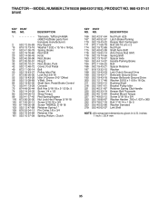
TRACTOR - - NO. DESCRIPTION 1 Transaxle, Tufftorq K46BA (408214)(Order parts from transaxle manufacturer) 2 532 12 35-83 Key Square 15 819 13 13-16 Washer 13/32 x 13/16 x 16 Ga. 17 532 41 36-...-12 Pin Cotter 1/8 x 3/4 160 532 16 94-84 Retainer Clip 161 532 10 57-09 Spring, Return, Clutch KEY PART NO. MODEL NUMBER LTH18538 (96043013102), PRODUCT NO. 960 43 01-31 DRIVE KEY PART NO. DESCRIPTION 166 532 42 91-64 Nut Push .625 167 532 40 52-57 Latch Brake Parking 170...
TRACTOR - - NO. DESCRIPTION 1 Transaxle, Tufftorq K46BA (408214)(Order parts from transaxle manufacturer) 2 532 12 35-83 Key Square 15 819 13 13-16 Washer 13/32 x 13/16 x 16 Ga. 17 532 41 36-...-12 Pin Cotter 1/8 x 3/4 160 532 16 94-84 Retainer Clip 161 532 10 57-09 Spring, Return, Clutch KEY PART NO. MODEL NUMBER LTH18538 (96043013102), PRODUCT NO. 960 43 01-31 DRIVE KEY PART NO. DESCRIPTION 166 532 42 91-64 Nut Push .625 167 532 40 52-57 Latch Brake Parking 170...
Owners Manual
Page 37
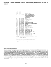
...conditions and engine-to-engine variability. Due to -engine variability. TRACTOR - - DESCRIPTION 1 Engine Briggs Model No. 31N707-1374-B1(429876) (Order parts from engine manufacturer) 2 532 13 73-52 Muffler 9 532 19 43-20 Keeper Belt Engine 12 532 40 54-71 Pulley Engine 15 532 ...been obtained and corrected in accordance with SAE J1995 (Revision 2002-05). MODEL NUMBER LTH18538 (96043013102), PRODUCT NO. 960 43 01-31 ENGINE KEY PART NO. inches 1 inch = 25.4 mm For engine service and replacement parts, call the toll free number for your engine manufacturer listed below: Briggs & Stratton...
...conditions and engine-to-engine variability. Due to -engine variability. TRACTOR - - DESCRIPTION 1 Engine Briggs Model No. 31N707-1374-B1(429876) (Order parts from engine manufacturer) 2 532 13 73-52 Muffler 9 532 19 43-20 Keeper Belt Engine 12 532 40 54-71 Pulley Engine 15 532 ...been obtained and corrected in accordance with SAE J1995 (Revision 2002-05). MODEL NUMBER LTH18538 (96043013102), PRODUCT NO. 960 43 01-31 ENGINE KEY PART NO. inches 1 inch = 25.4 mm For engine service and replacement parts, call the toll free number for your engine manufacturer listed below: Briggs & Stratton...
Owners Manual
Page 39
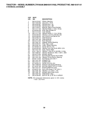
... Nut Lock Flange 7/16-14 Gr. 5 Washer 1.5 x .505 x .118 Bracket Deck Susp. inches 1 inch = 25.4 mm 39 Supt. MODEL NUMBER LTH18538 (96043013102), PRODUCT NO. 960 43 01-31 STEERING ASSEMBLY KEY PART NO. NO. 1 532 43 79-97 2 532 19 59-68 4 532 40 30-87 5 532 40 30-88 6 532 12...
... Nut Lock Flange 7/16-14 Gr. 5 Washer 1.5 x .505 x .118 Bracket Deck Susp. inches 1 inch = 25.4 mm 39 Supt. MODEL NUMBER LTH18538 (96043013102), PRODUCT NO. 960 43 01-31 STEERING ASSEMBLY KEY PART NO. NO. 1 532 43 79-97 2 532 19 59-68 4 532 40 30-87 5 532 40 30-88 6 532 12...
Owners Manual
Page 41
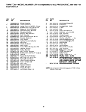
ing, shaft assembly, and bearing only - MODEL NUMBER LTH18538 (96043013102), PRODUCT NO. 960 43 01-31 MOWER DECK KEY PART NO. DESCRIPTION 63 532 19 94-70 Arm Brake Mower RH 64 532 19 99-18 Link Brake 67 532 40 30-12 Handle Clutch ... 57 817 00 06-16 Screw 3/8-16 x 1 59 532 14 10-43 Guard, Tuv Idler 60 532 19 94-71 Arm Brake Mower LH KEY PART NO. NO. pulley/nut/washer and blade bolt/washers not included) - - 532 41 07-16 Replacement Mower, Complete NOTE: All component dimensions given in U.S. inches...
ing, shaft assembly, and bearing only - MODEL NUMBER LTH18538 (96043013102), PRODUCT NO. 960 43 01-31 MOWER DECK KEY PART NO. DESCRIPTION 63 532 19 94-70 Arm Brake Mower RH 64 532 19 99-18 Link Brake 67 532 40 30-12 Handle Clutch ... 57 817 00 06-16 Screw 3/8-16 x 1 59 532 14 10-43 Guard, Tuv Idler 60 532 19 94-71 Arm Brake Mower LH KEY PART NO. NO. pulley/nut/washer and blade bolt/washers not included) - - 532 41 07-16 Replacement Mower, Complete NOTE: All component dimensions given in U.S. inches...


