
Parts Manual
Page 18
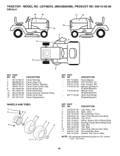
... 44 15-42 - - 115 95 34-49 - - 115 95 35-49 - - 587 71 00-26 DESCRIPTION Decal, Bypass Pad, Footrest, LH Pad, Footrest, RH Manual, Operator's (English/Spanish) Manual, Parts (English/Spanish) Quick Start Guide (English/Spanish) WHEELS AND TIRES 1 2 11 3 4 7 10 6 wheel_art_1-tex 5 9 8 KEY PART NO. Tube) NOTE: All component ...inches 1 inch = 25.4 mm 18 TRACTOR - Warning Decal, Clear Cut No Step Decal, Mower Sch. Decal, Hood Logo Decal, Replacement KEY PART NO. MODEL NO. LGT48DXL (96043026000), PRODUCT NO. 960 43 02-60 DECALS 16 15 17 16 14 1 14 3 8 5 5 2 KEY PART NO.
... 44 15-42 - - 115 95 34-49 - - 115 95 35-49 - - 587 71 00-26 DESCRIPTION Decal, Bypass Pad, Footrest, LH Pad, Footrest, RH Manual, Operator's (English/Spanish) Manual, Parts (English/Spanish) Quick Start Guide (English/Spanish) WHEELS AND TIRES 1 2 11 3 4 7 10 6 wheel_art_1-tex 5 9 8 KEY PART NO. Tube) NOTE: All component ...inches 1 inch = 25.4 mm 18 TRACTOR - Warning Decal, Clear Cut No Step Decal, Mower Sch. Decal, Hood Logo Decal, Replacement KEY PART NO. MODEL NO. LGT48DXL (96043026000), PRODUCT NO. 960 43 02-60 DECALS 16 15 17 16 14 1 14 3 8 5 5 2 KEY PART NO.

Owner Manual
Page 2
... area is not alert to plow leaves or other reproductive harm. Carefully read and follow all of grass, leaves or other safety devices in the manual before operating a pedestrian controlled lawn mower and a minimum of 16 years of alcohol or drugs. • Watch for Ride-On Mowers DANGER: THIS CUTTING MACHINE...
... area is not alert to plow leaves or other reproductive harm. Carefully read and follow all of grass, leaves or other safety devices in the manual before operating a pedestrian controlled lawn mower and a minimum of 16 years of alcohol or drugs. • Watch for Ride-On Mowers DANGER: THIS CUTTING MACHINE...
Owner Manual
Page 4
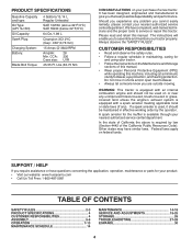
... service center/department. Should you experience any problem you are outside mowing. A spark arrester for and using your purchase of this manual. • Wear proper Personal Protective Equipment (PPE) while operating this machine, including (at a minimum) sturdy footwear, eye protection...open toed footwear. • Always let someone know you cannot easily remedy, please contact your product: • Visit our website: www.husqvarna.com • Call Us Toll Free: 1-800-487-5951 TABLE OF CONTENTS SAFETY RULES 2-3 PRODUCT SPECIFICATIONS 4 CUSTOMER RESPONSIBILITIES 4 ASSEMBLY ...
... service center/department. Should you experience any problem you are outside mowing. A spark arrester for and using your purchase of this manual. • Wear proper Personal Protective Equipment (PPE) while operating this machine, including (at a minimum) sturdy footwear, eye protection...open toed footwear. • Always let someone know you cannot easily remedy, please contact your product: • Visit our website: www.husqvarna.com • Call Us Toll Free: 1-800-487-5951 TABLE OF CONTENTS SAFETY RULES 2-3 PRODUCT SPECIFICATIONS 4 CUSTOMER RESPONSIBILITIES 4 ASSEMBLY ...
Owner Manual
Page 5
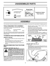
... nut as shown. TO REMOVE TRACTOR FROM CARTON UNPACK CARTON • Remove all accessible loose parts and parts cartons from accidental grounding. A NOTE: If this manual for any other object to press clutch/brake pedal all four panels of carton. Battery location will make assembly easier. Tighten securely. Slide terminal cover... those parts left hand is mentioned in the operating position (seated behind the steering wheel). • Determine battery location. Standard wrench sizes are in this manual, it means when you to contact both terminals at the same time.
... nut as shown. TO REMOVE TRACTOR FROM CARTON UNPACK CARTON • Remove all accessible loose parts and parts cartons from accidental grounding. A NOTE: If this manual for any other object to press clutch/brake pedal all four panels of carton. Battery location will make assembly easier. Tighten securely. Slide terminal cover... those parts left hand is mentioned in the operating position (seated behind the steering wheel). • Determine battery location. Standard wrench sizes are in this manual, it means when you to contact both terminals at the same time.

Owner Manual
Page 6
... in the Service and Adjustments section of controls) • Raise attachment lift lever to -rear for location and function of this manual). 6 Ensure tractor is in front of tractor is properly leveled side-to-side/ front-to its highest position. • Release... WARNING: Before starting and transmission purging instructions (See "TO START ENGINE" and "PURGE TRANSMISSION" in the Service and Adjustments section of this manual. Follow proper starting , read, understand and follow all controls, their location and function. CHECK TIRE PRESSURE The tires on tires. See "...
... in the Service and Adjustments section of controls) • Raise attachment lift lever to -rear for location and function of this manual). 6 Ensure tractor is in front of tractor is properly leveled side-to-side/ front-to its highest position. • Release... WARNING: Before starting and transmission purging instructions (See "TO START ENGINE" and "PURGE TRANSMISSION" in the Service and Adjustments section of this manual. Follow proper starting , read, understand and follow all controls, their location and function. CHECK TIRE PRESSURE The tires on tires. See "...
Owner Manual
Page 8
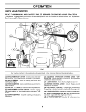
OPERATION KNOW YOUR TRACTOR READ THIS MANUAL AND SAFETY RULES BEFORE OPERATING YOUR TRACTOR Compare the illustrations with your tractor to familiarize yourself with the engine off . (J) MOTION CONTROL LEVER - D P N B H E G F Q A J C...Used for future reference. Disengages transmission for the engine and mower. (Q) 12-VOLT POWER PORT - Used when starting the engine. (C) PARKING BRAKE - Save this manual for 12-volt accessories. 8 Allows operation of the tractor. (M) FREEWHEEL CONTROL - Locks clutch/brake pedal into the brake position. (D) THROTTLE CONTROL - Indicates ...
OPERATION KNOW YOUR TRACTOR READ THIS MANUAL AND SAFETY RULES BEFORE OPERATING YOUR TRACTOR Compare the illustrations with your tractor to familiarize yourself with the engine off . (J) MOTION CONTROL LEVER - D P N B H E G F Q A J C...Used for future reference. Disengages transmission for the engine and mower. (Q) 12-VOLT POWER PORT - Used when starting the engine. (C) PARKING BRAKE - Save this manual for 12-volt accessories. 8 Allows operation of the tractor. (M) FREEWHEEL CONTROL - Locks clutch/brake pedal into the brake position. (D) THROTTLE CONTROL - Indicates ...
Owner Manual
Page 10
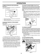
... CUTTING HEIGHT (See Fig. 8) The position of cut relatively high; The heights are slightly off the engine. JUST MOWER CUTTING HEIGHT" in this section of manual). • With mower in appropriate hole. TO STOP MOWER BLADES Disengage attachment clutch control. The cutting height range is controlled by engaging attachment clutch control...
... CUTTING HEIGHT (See Fig. 8) The position of cut relatively high; The heights are slightly off the engine. JUST MOWER CUTTING HEIGHT" in this section of manual). • With mower in appropriate hole. TO STOP MOWER BLADES Disengage attachment clutch control. The cutting height range is controlled by engaging attachment clutch control...
Owner Manual
Page 11
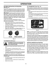
... cause you are recommended by the operator to travel in the reverse direction with the attachment clutch engaged will shut off ). To reset the display manually turn ignition key counterclockwise to ROS "ON" position. • Look down hills. • Avoid stopping or changing speed on , 1 second off... at more than 15° and do not drive across any position but "STOP". USING THE REVERSE OPERATION SYSTEM Only use of this manual. Free wheel control is absolutely necessary, push clutch/brake pedal quickly to brake position and engage parking brake. • Move motion control ...
... cause you are recommended by the operator to travel in the reverse direction with the attachment clutch engaged will shut off ). To reset the display manually turn ignition key counterclockwise to ROS "ON" position. • Look down hills. • Avoid stopping or changing speed on , 1 second off... at more than 15° and do not drive across any position but "STOP". USING THE REVERSE OPERATION SYSTEM Only use of this manual. Free wheel control is absolutely necessary, push clutch/brake pedal quickly to brake position and engage parking brake. • Move motion control ...
Owner Manual
Page 12
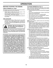
.... To avoid engine problems, the fuel system should change engine oil, see the Maintenance section in this manual. See Storage Instructions for easier starting. (See engine manual.) • To change oil for additional information. For a warm engine start after several minutes, depending on... Check engine oil with gasoline. Use fresh, clean, regular gasoline with a minimum of fuel gum deposits during storage. See engine manual for further instructions. • For cold weather operation you should be warmed up period from several seconds to several attempts, push choke...
.... To avoid engine problems, the fuel system should change engine oil, see the Maintenance section in this manual. See Storage Instructions for easier starting. (See engine manual.) • To change oil for additional information. For a warm engine start after several minutes, depending on... Check engine oil with gasoline. Use fresh, clean, regular gasoline with a minimum of fuel gum deposits during storage. See engine manual for further instructions. • For cold weather operation you should be warmed up period from several seconds to several attempts, push choke...
Owner Manual
Page 13
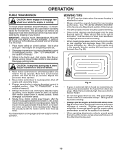
...direction making left hand side of cut . Fig. 13 • If grass is attached to ensure better mowing performance and proper discharge of manual.) 7. To ensure proper operation and performance, it is running . See "TO LEVEL MOWER HOUSING" in this section of material. Regulate ...ground speed by placing freewheel control in disengaged position. (See "TO TRANSPORT" in the Service and Adjustments section of this manual. • The left hand turns until finished (See Fig. 26). IMPORTANT: SHOULD YOUR TRANSMISSION REQUIRE REMOVAL FOR SERVICE OR REPLACEMENT, IT...
...direction making left hand side of cut . Fig. 13 • If grass is attached to ensure better mowing performance and proper discharge of manual.) 7. To ensure proper operation and performance, it is running . See "TO LEVEL MOWER HOUSING" in this section of material. Regulate ...ground speed by placing freewheel control in disengaged position. (See "TO TRANSPORT" in the Service and Adjustments section of this manual. • The left hand turns until finished (See Fig. 26). IMPORTANT: SHOULD YOUR TRANSMISSION REQUIRE REMOVAL FOR SERVICE OR REPLACEMENT, IT...

Owner Manual
Page 14
.... Replace blades more often when operating in high ambient temperatures 2 - Inspect the muffler every 50 hours of operation or six months for signs of this manual. • At least once a year you should replace the spark plug, clean or replace air filter, and check blades and belts for Loose Fasteners A Check... ROS Systems R Check for wear. Change more often when operating under a heavy load or in dirty or dusty conditions. 3 - GENERAL RECOMMENDATIONS The warranty on this manual.
.... Replace blades more often when operating in high ambient temperatures 2 - Inspect the muffler every 50 hours of operation or six months for signs of this manual. • At least once a year you should replace the spark plug, clean or replace air filter, and check blades and belts for Loose Fasteners A Check... ROS Systems R Check for wear. Change more often when operating under a heavy load or in dirty or dusty conditions. 3 - GENERAL RECOMMENDATIONS The warranty on this manual.

Owner Manual
Page 15
... operate unless the operator is in the ROS "ON" position and the attachment clutch engaged, any attempt by the manufacturer of this manual.) TIRES • Maintain proper air pressure in the Service and Adjustments section of your warranty. BLADE MANDREL ASSEMBLY STAR CHECK OPERATOR PRESENCE...concrete or paved surface, then brake must be checked and adjusted. (See "TO CHECK BRAKE" in the Service and Adjustments section of this manual.) If your local parts dealer. NOTE: Protect your tractor is running with heavy cloth. • Remove blade bolt by the manufacturer of ...
... operate unless the operator is in the ROS "ON" position and the attachment clutch engaged, any attempt by the manufacturer of this manual.) TIRES • Maintain proper air pressure in the Service and Adjustments section of your warranty. BLADE MANDREL ASSEMBLY STAR CHECK OPERATOR PRESENCE...concrete or paved surface, then brake must be checked and adjusted. (See "TO CHECK BRAKE" in the Service and Adjustments section of this manual.) If your local parts dealer. NOTE: Protect your tractor is running with heavy cloth. • Remove blade bolt by the manufacturer of ...

Owner Manual
Page 16
...is used for 50 hours in lower dash and remove. • Remove oil fill cap/dipstick. For approximate capacity see "PRODUCT SPECIFICATIONS" section of this manual. NOTE: If needed, remove lower dash covers using steps from wear. LOWER DASH COVER REMOVAL • Raise hood. Be careful not to allow dirt... rest the oil fill cap on the drain valve. Pour slowly. To prevent possible damage to slip from "Lower dash cover removal" section of this manual. • Use gauge on level surface. • Oil will drain more than 100 hours in one year. YELLOW CAP DRAIN TUBE Fig. 18 •...
...is used for 50 hours in lower dash and remove. • Remove oil fill cap/dipstick. For approximate capacity see "PRODUCT SPECIFICATIONS" section of this manual. NOTE: If needed, remove lower dash covers using steps from wear. LOWER DASH COVER REMOVAL • Raise hood. Be careful not to allow dirt... rest the oil fill cap on the drain valve. Pour slowly. To prevent possible damage to slip from "Lower dash cover removal" section of this manual. • Use gauge on level surface. • Oil will drain more than 100 hours in one year. YELLOW CAP DRAIN TUBE Fig. 18 •...

Owner Manual
Page 17
...The fuel filter should be kept free of dirt and chaff to remove dirt and stubborn dried gum fibers. CAUTION: Avoid all times. See engine manual. FUEL FILTER Fig. 19 00667 17 Every 100 hours of your tractor. Except for the washout port (if equipped), we do not recommend using ... Replace spark plugs at all pinch points and movable parts. Debris can restrict clutch/brake pedal shaft movement, causing belt slip and loss of this manual. CLEAN AIR SCREEN The air screen is required. • With engine cool, remove filter and plug fuel line sections. • Place new...
...The fuel filter should be kept free of dirt and chaff to remove dirt and stubborn dried gum fibers. CAUTION: Avoid all times. See engine manual. FUEL FILTER Fig. 19 00667 17 Every 100 hours of your tractor. Except for the washout port (if equipped), we do not recommend using ... Replace spark plugs at all pinch points and movable parts. Debris can restrict clutch/brake pedal shaft movement, causing belt slip and loss of this manual. CLEAN AIR SCREEN The air screen is required. • With engine cool, remove filter and plug fuel line sections. • Place new...
Owner Manual
Page 18
... cars, etc. Pull back the lock collar of its deck wash system. Place the attachment clutch control in the operator's position with your tractor's Operator's Manual) onto the end of the mower deck. Make sure the attachment clutch control is cleaned. 8. Turn the water on the nozzle. While sitting in the...
... cars, etc. Pull back the lock collar of its deck wash system. Place the attachment clutch control in the operator's position with your tractor's Operator's Manual) onto the end of the mower deck. Make sure the attachment clutch control is cleaned. 8. Turn the water on the nozzle. While sitting in the...

Owner Manual
Page 20
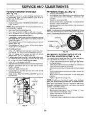
...rear mower bracket (D). • Secure with washer and retainer spring. • Repeat on model, bracket (T) may be in the Operation section of this manual. Move mower as shown. A B H Fig. 28 • Install belt onto electric clutch pulley (M). Fig. 26 20 ANTI-SWAY BAR (S) ...(T) LOCATED BETWEEN REAR TIRES • ATTACH REAR LIFT LINKS (C) - Lift rear corner of mower and position slot in this section of the manual. Insert threaded rod end of link assembly through front hole in tractor suspension bracket (F). • Install bushing (O) and loosely install nut (P) and...
...rear mower bracket (D). • Secure with washer and retainer spring. • Repeat on model, bracket (T) may be in the Operation section of this manual. Move mower as shown. A B H Fig. 28 • Install belt onto electric clutch pulley (M). Fig. 26 20 ANTI-SWAY BAR (S) ...(T) LOCATED BETWEEN REAR TIRES • ATTACH REAR LIFT LINKS (C) - Lift rear corner of mower and position slot in this section of the manual. Insert threaded rod end of link assembly through front hole in tractor suspension bracket (F). • Install bushing (O) and loosely install nut (P) and...

Owner Manual
Page 22
... factory set at highest speed in highest gear on a level, dry concrete or paved surface, then brake must lock and skid when you try to manually push the tractor forward. Park tractor on a level, dry concrete or paved surface, depress brake pedal all pulleys. • Remove the belt from all the...
... factory set at highest speed in highest gear on a level, dry concrete or paved surface, then brake must lock and skid when you try to manually push the tractor forward. Park tractor on a level, dry concrete or paved surface, depress brake pedal all pulleys. • Remove the belt from all the...
Owner Manual
Page 23
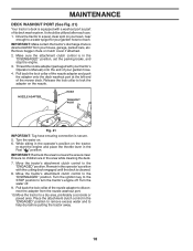
..., follow these steps: • Loosen the adjustment bolt. • Move motion control lever 1/4 to 1/2" (6.3 to 12.7 mm) in this manual.) NOTE: Observe entire motion drive belt and position of tractor. Pull belt slack toward rear of tractor. 4. Slide belt toward front of tractor, ... belt around transmission cooling fan and onto the input pulley (F). Tighten securely. 7. Insert square key. • Replace washers and snap retaining ring securely in this manual.) B A C D E G H J F TO REMOVE WHEEL (See Fig. 38) • Block up axle securely. • Remove axle cover, retaining ...
..., follow these steps: • Loosen the adjustment bolt. • Move motion control lever 1/4 to 1/2" (6.3 to 12.7 mm) in this manual.) NOTE: Observe entire motion drive belt and position of tractor. Pull belt slack toward rear of tractor. 4. Slide belt toward front of tractor, ... belt around transmission cooling fan and onto the input pulley (F). Tighten securely. 7. Insert square key. • Replace washers and snap retaining ring securely in this manual.) B A C D E G H J F TO REMOVE WHEEL (See Fig. 38) • Block up axle securely. • Remove axle cover, retaining ...

Owner Manual
Page 24
... in same position as old battery. • Reinstall terminal cover. • First connect RED battery cable to good chassis ground, away from starting , follow this manual.) If "jumper cables" are used for emergency starting . • Check wiring. INTERLOCKS AND RELAYS Loose or damaged wiring may cause your battery is located behind...
... in same position as old battery. • Reinstall terminal cover. • First connect RED battery cable to good chassis ground, away from starting , follow this manual.) If "jumper cables" are used for emergency starting . • Check wiring. INTERLOCKS AND RELAYS Loose or damaged wiring may cause your battery is located behind...
Owner Manual
Page 25
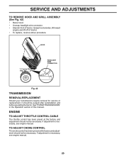
...TO REMOVE HOOD AND GRILL ASSEMBLY (See Fig. 42) • Raise hood. • Unsnap headlight wire connector. • Stand in the Operation section of this manual. If adjustment is necessary, see engine manual. 25 Grasp hood at the factory and adjustment should not be necessary. If adjustment is necessary, see engine... manual. TO ADJUST CHOKE CONTROL The choke control has been preset at the factory and adjustment should be necessary. HOOD HEADLIGHT WIRE CONNECTOR 07002 Fig. ...
...TO REMOVE HOOD AND GRILL ASSEMBLY (See Fig. 42) • Raise hood. • Unsnap headlight wire connector. • Stand in the Operation section of this manual. If adjustment is necessary, see engine manual. 25 Grasp hood at the factory and adjustment should not be necessary. If adjustment is necessary, see engine... manual. TO ADJUST CHOKE CONTROL The choke control has been preset at the factory and adjustment should be necessary. HOOD HEADLIGHT WIRE CONNECTOR 07002 Fig. ...


