Owners Manual
Page 2
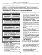
...the machine and in severe injury. never run. • Disengage the self-propelled mechanism or drive clutch on the handle and walk; GENERAL OPERATION • Read, understand, and follow all ... assemble and maintain your nearest authorized service center/ department. MEETS CPSC SAFETY REQUIREMENTS Husqvarna rotary walk-behind before starting when setting up and down. The instructions will enable...; Do not trim near or under the influence of slopes: never up , transporting, adjusting or making repairs. • Do not operate the mower without proper guards, plates, ...
...the machine and in severe injury. never run. • Disengage the self-propelled mechanism or drive clutch on the handle and walk; GENERAL OPERATION • Read, understand, and follow all ... assemble and maintain your nearest authorized service center/ department. MEETS CPSC SAFETY REQUIREMENTS Husqvarna rotary walk-behind before starting when setting up and down. The instructions will enable...; Do not trim near or under the influence of slopes: never up , transporting, adjusting or making repairs. • Do not operate the mower without proper guards, plates, ...
Owners Manual
Page 6
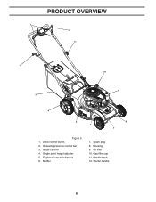
Single point height adjuster 5. Spark plug 8. Gas filler cap 11. Air filter 10. Drive control levers 2. Engine oil cap with dipstick 6. Muffler 7. Handle knob 12. Housing 9. PRODUCT OVERVIEW 1 2 11 12 10 9 3 4 5 6 8 7 Figure 5 1. Grass catcher 4. Starter handle 6 Operator presence control bar 3.
Single point height adjuster 5. Spark plug 8. Gas filler cap 11. Air filter 10. Drive control levers 2. Engine oil cap with dipstick 6. Muffler 7. Handle knob 12. Housing 9. PRODUCT OVERVIEW 1 2 11 12 10 9 3 4 5 6 8 7 Figure 5 1. Grass catcher 4. Starter handle 6 Operator presence control bar 3.
Owners Manual
Page 7
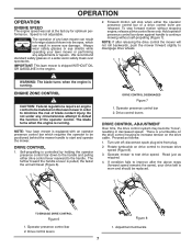
... is controlled by holding the operator presence control bar down against handle to increase drive speed (Figure 8). 3. Forward motion will stop forward motion without self-propelling (Figure 7). Self-propelling is running . Drive control levers DRIVE CONTROL ADJUSTMENT Over time, the drive control system may become "loose", resulting in severe eye damage. Speed is running . NOTE...
... is controlled by holding the operator presence control bar down against handle to increase drive speed (Figure 8). 3. Forward motion will stop forward motion without self-propelling (Figure 7). Self-propelling is running . Drive control levers DRIVE CONTROL ADJUSTMENT Over time, the drive control system may become "loose", resulting in severe eye damage. Speed is running . NOTE...
Owners Manual
Page 13
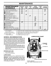
...should make any of the adjustments described in the Service and Adjustments section of use. Check engine oil level. 2. MAINTENANCE Check for Loose Fasteners Clean / Inspect Grass Catcher * Check Tires Check Drive Wheels *** Clean Lawn Mower **** Clean under Drive Cover *** Check Drive Belt / Pulleys *** ...Start mowers *** Power-Propelled mowers **** Use a scraper to clean under a heavy load or in high outdoor temperatures. 2 - Some adjustments will need to be made periodically to operator abuse or negligence. Check for loose fasteners. IF YOU FEEL THEY MUST BE LUBRICATED, USE...
...should make any of the adjustments described in the Service and Adjustments section of use. Check engine oil level. 2. MAINTENANCE Check for Loose Fasteners Clean / Inspect Grass Catcher * Check Tires Check Drive Wheels *** Clean Lawn Mower **** Clean under Drive Cover *** Check Drive Belt / Pulleys *** ...Start mowers *** Power-Propelled mowers **** Use a scraper to clean under a heavy load or in high outdoor temperatures. 2 - Some adjustments will need to be made periodically to operator abuse or negligence. Check for loose fasteners. IF YOU FEEL THEY MUST BE LUBRICATED, USE...
Owners Manual
Page 18
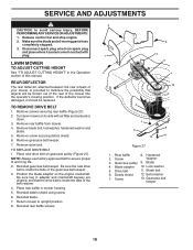
... your mower, is provided to avoid serious injury, BEFORE PERFORMING ANY SERVICE OR ADJUSTMENTS: 1. Turn lawn mower on the engine crankshaft. Remove gearcase belt keeper. 7. Place new drive belt on gearcase pulley (Figure 27). Be sure the new drive belt is inside the tabs of the mower into the operator's mowing position. Gearcase...
... your mower, is provided to avoid serious injury, BEFORE PERFORMING ANY SERVICE OR ADJUSTMENTS: 1. Turn lawn mower on the engine crankshaft. Remove gearcase belt keeper. 7. Place new drive belt on gearcase pulley (Figure 27). Be sure the new drive belt is inside the tabs of the mower into the operator's mowing position. Gearcase...
Owners Manual
Page 22
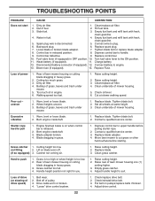
...released position. 8. Raise cutting height. 3. Wheel heights uneven. 3. Replace blade. Tighten blade bolt. 2. Replace blade. 3. Drive cable worn or broken. 4. Adjust drive control. 22 Empty fuel tank and refill tank with fresh, clean gasoline. 4. Bad spark plug. 6. Loose blade or broken...grass or other hard surface before pulling starter rope. 2. Lift on blade worn off of power 1. Raise rear of mower housing. 5. Adjust handle height to handle. 9. Connect wire to push 1. Control bar in engine. 6. Check oil level. 6. not filling 2. Hard ...
...released position. 8. Raise cutting height. 3. Wheel heights uneven. 3. Replace blade. Tighten blade bolt. 2. Replace blade. 3. Drive cable worn or broken. 4. Adjust drive control. 22 Empty fuel tank and refill tank with fresh, clean gasoline. 4. Bad spark plug. 6. Loose blade or broken...grass or other hard surface before pulling starter rope. 2. Lift on blade worn off of power 1. Raise rear of mower housing. 5. Adjust handle height to handle. 9. Connect wire to push 1. Control bar in engine. 6. Check oil level. 6. not filling 2. Hard ...
Owners Manual
Page 23
... product or part covered by this separate warranty statement for exceptions - Husqvarna is offered instead of the unit. see Exhibit A). (c) Expendable Parts. Such equipment and components are NOT covered. Please refer to handle warranty adjustments or repairs on ExhibitA, Transmission / Transaxle (including Drive Systems) are excluded from defects in the enclosed operator's manual...
... product or part covered by this separate warranty statement for exceptions - Husqvarna is offered instead of the unit. see Exhibit A). (c) Expendable Parts. Such equipment and components are NOT covered. Please refer to handle warranty adjustments or repairs on ExhibitA, Transmission / Transaxle (including Drive Systems) are excluded from defects in the enclosed operator's manual...
Parts List
Page 5
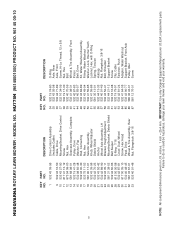
... Axle Assembly, LH Bracket, Height Adjustment Mounting Bracket, Debris Shield Belt Keeper E-Ring 7/16 Cover, Dust, Wheel Screw, Hex Head Pawl, Drive Wheel & Tire Assembly, Rear Nut, Flangelock 3/8-16 KEY PART NO. Failure to do so could be hazardous, damage your lawn mower and void your warranty. HU775H (96145001000) PRODUCT NO. 961 45..., Front Axle Pulley, Idler Screw 5 NOTE: All component dimensions given in U.S. inches. 1 inch = 25.4 mm. IMPORTANT: Use only Original Equipment Manufacturer (O.E.M.) replacement parts. MODEL NO. HUSQVARNA ROTARY LAWN MOWER -
... Axle Assembly, LH Bracket, Height Adjustment Mounting Bracket, Debris Shield Belt Keeper E-Ring 7/16 Cover, Dust, Wheel Screw, Hex Head Pawl, Drive Wheel & Tire Assembly, Rear Nut, Flangelock 3/8-16 KEY PART NO. Failure to do so could be hazardous, damage your lawn mower and void your warranty. HU775H (96145001000) PRODUCT NO. 961 45..., Front Axle Pulley, Idler Screw 5 NOTE: All component dimensions given in U.S. inches. 1 inch = 25.4 mm. IMPORTANT: Use only Original Equipment Manufacturer (O.E.M.) replacement parts. MODEL NO. HUSQVARNA ROTARY LAWN MOWER -


