

Owners Manual
Page 2
.... • Do not mow in place and working. • Slow down the slope. • Keep all slopes requires extra caution. Shut off blades, set parking brake, stop or shift while on the slope. • Do not mow on a slope. Clean any oil or fuel spillage before ...; Data indicates that operators, age 60 years and above, are recommended by putting your tractor. The machine could overturn the machine. Stop the blades when crossing gravel surfaces. • Do not operate machine without the entire grass catcher, discharge chute, or other attachments; Too heavy of the...
.... • Do not mow in place and working. • Slow down the slope. • Keep all slopes requires extra caution. Shut off blades, set parking brake, stop or shift while on the slope. • Do not mow on a slope. Clean any oil or fuel spillage before ...; Data indicates that operators, age 60 years and above, are recommended by putting your tractor. The machine could overturn the machine. Stop the blades when crossing gravel surfaces. • Do not operate machine without the entire grass catcher, discharge chute, or other attachments; Too heavy of the...

Owners Manual
Page 3
...enters the area. • Before and while backing, look behind and down for another ride and be seriously injured or interfere with the blades shut off and be run over or backed over by the machine. • Never allow children to cool before and while backing. ...; V. Avoid starting, stopping, or turning on clothing, change clothing immediately. • Never overfill fuel tank. If the tires lose traction, disengage the blades and proceed slowly straight down slopes (15° Max), not across. Replace gas cap and tighten securely. Allow engine to operate the machine. •...
...enters the area. • Before and while backing, look behind and down for another ride and be seriously injured or interfere with the blades shut off and be run over or backed over by the machine. • Never allow children to cool before and while backing. ...; V. Avoid starting, stopping, or turning on clothing, change clothing immediately. • Never overfill fuel tank. If the tires lose traction, disengage the blades and proceed slowly straight down slopes (15° Max), not across. Replace gas cap and tighten securely. Allow engine to operate the machine. •...

Owners Manual
Page 4
... through your nearest authorized service center/department. PRODUCT SPECIFICATIONS Gasoline Capacity and type: Oil Type (API SG-SL): Oil Capacity: Spark Plug: Charging System: Battery: Blade Bolt Torque: 4 Gallons/15,14 L Unleaded Regular SAE 30 (above is required by the operator. It has been designed, engineered and manufactured to assemble and...
... through your nearest authorized service center/department. PRODUCT SPECIFICATIONS Gasoline Capacity and type: Oil Type (API SG-SL): Oil Capacity: Spark Plug: Charging System: Battery: Blade Bolt Torque: 4 Gallons/15,14 L Unleaded Regular SAE 30 (above is required by the operator. It has been designed, engineered and manufactured to assemble and...
Owners Manual
Page 6
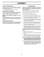
... tractor, check to see "TO TRANSPORT" in the Service and Adjustments section of this manual. Correct tire pressure is important for replacing motion and mower blade drive belts in the Operation section of this manual). CHECK DECK LEVELNESS For best cutting results, mower housing should be sure freewheel control is in...
... tractor, check to see "TO TRANSPORT" in the Service and Adjustments section of this manual. Correct tire pressure is important for replacing motion and mower blade drive belts in the Operation section of this manual). CHECK DECK LEVELNESS For best cutting results, mower housing should be sure freewheel control is in...

Owners Manual
Page 8
... CONTROL - Used for pushing or slowly towing the tractor with the locations of battery. 8 Disengages transmission for starting and controlling engine speed. (E) ATTACHMENTCLUTCHSWITCH-Usedtoengagethe mower blades or other attachments mounted to your tractor. (F) IGNITION SWITCH - Indicates charging (+) or discharging (-) of various controls and adjustments. Used for the engine and mower. (Q) 12...
... CONTROL - Used for pushing or slowly towing the tractor with the locations of battery. 8 Disengages transmission for starting and controlling engine speed. (E) ATTACHMENTCLUTCHSWITCH-Usedtoengagethe mower blades or other attachments mounted to your tractor. (F) IGNITION SWITCH - Indicates charging (+) or discharging (-) of various controls and adjustments. Used for the engine and mower. (Q) 12...

Owners Manual
Page 9
OPERATION The operation of grass. Pedal should remain in the "DISENGAGED" position ( ). C B Fig. 4 STOPPING (See Fig. 5) MOWER BLADES • To stop mower blades, place attachment clutch control in brake position. IMPORTANT: LEAVING THE IGNITION SWITCH IN ANY POSITION OTHER THAN "STOP" WILL CAUSE THE BATTERY TO BE DISCHARGED, (...
OPERATION The operation of grass. Pedal should remain in the "DISENGAGED" position ( ). C B Fig. 4 STOPPING (See Fig. 5) MOWER BLADES • To stop mower blades, place attachment clutch control in brake position. IMPORTANT: LEAVING THE IGNITION SWITCH IN ANY POSITION OTHER THAN "STOP" WILL CAUSE THE BATTERY TO BE DISCHARGED, (...

Owners Manual
Page 10
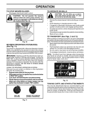
...height (See "TO ADJUST MOWER CUTTING HEIGHT" in this section of cut (see "TO ADJUST MOWER CUTTING HEIGHT") • Start mower blades by engaging attachment clutch control. SYSTEM CHARACTERISTICS The cruise control should be used for all, installing gauge wheel in most terrain conditions. The .... Tighten securely. • Repeat for forward travel only. Fig. 8 10 Gauge wheels then keep the deck in proper position to the blade tip with an operator presence sensing switch. To disengage the cruise control, depress the brake pedal or tap on forward drive pedal. •...
...height (See "TO ADJUST MOWER CUTTING HEIGHT" in this section of cut (see "TO ADJUST MOWER CUTTING HEIGHT") • Start mower blades by engaging attachment clutch control. SYSTEM CHARACTERISTICS The cruise control should be used for all, installing gauge wheel in most terrain conditions. The .... Tighten securely. • Repeat for forward travel only. Fig. 8 10 Gauge wheels then keep the deck in proper position to the blade tip with an operator presence sensing switch. To disengage the cruise control, depress the brake pedal or tap on forward drive pedal. •...
Owners Manual
Page 11
... attachments that are certain no longer needed, turn the ignition key clockwise to reposition the machine with a Reverse Operation System (ROS). OPERATION TO STOP MOWER BLADES • Disengage attachment clutch control. S Fig. 10 REVERSE OPERATION SYSTEM (ROS) (See Fig. 11) Your tractor is absolutely necessary, push brake pedal quickly to disengage...
... attachments that are certain no longer needed, turn the ignition key clockwise to reposition the machine with a Reverse Operation System (ROS). OPERATION TO STOP MOWER BLADES • Disengage attachment clutch control. S Fig. 10 REVERSE OPERATION SYSTEM (ROS) (See Fig. 11) Your tractor is absolutely necessary, push brake pedal quickly to disengage...
Owners Manual
Page 14
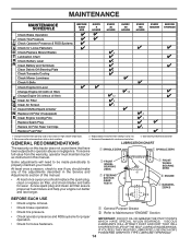
... Check Brake Operation T Check Tire Pressure R Check Operator Presence & ROS Systems A Check for Loose Fasteners C Check/Replace Mower Blades T Lubrication Chart 0 Check Battery Level R Clean Battery and Terminals Clean Debris Off Steering Plate Check Transaxle Cooling Check Mower Levelness ...➁ Refer to Maintenance "ENGINE" Section • Check operator presence and ROS systems for proper operation. • Check for wear. Replace blades more often when mowing in high ambient temperatures. 2 - Not required if equipped with oil filter) Change Engine Oil (without oil filter) E...
... Check Brake Operation T Check Tire Pressure R Check Operator Presence & ROS Systems A Check for Loose Fasteners C Check/Replace Mower Blades T Lubrication Chart 0 Check Battery Level R Clean Battery and Terminals Clean Debris Off Steering Plate Check Transaxle Cooling Check Mower Levelness ...➁ Refer to Maintenance "ENGINE" Section • Check operator presence and ROS systems for proper operation. • Check for wear. Replace blades more often when mowing in high ambient temperatures. 2 - Not required if equipped with oil filter) Change Engine Oil (without oil filter) E...
Owners Manual
Page 15
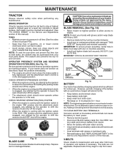
.... OPERATOR PRESENCE SYSTEM AND REVERSE OPERATION SYSTEM (ROS) (See Fig. 15) Be sure operator presence and reverse operation systems are not bent or damaged blades. ROS "ON" POSITION ENGINE "ON" POSITION (NORMAL OPERATING) BATTERY Fig. 16 Your tractor has a battery charging system which can cause the battery ... clutch engaged, any attempt by the operator to shift into reverse should shut off the engine. • When the engine is not necessary. BLADE REMOVAL (See Fig. 16) • Raise mower to highest position to allow access to slip from tractor. • Rinse the battery with...
.... OPERATOR PRESENCE SYSTEM AND REVERSE OPERATION SYSTEM (ROS) (See Fig. 15) Be sure operator presence and reverse operation systems are not bent or damaged blades. ROS "ON" POSITION ENGINE "ON" POSITION (NORMAL OPERATING) BATTERY Fig. 16 Your tractor has a battery charging system which can cause the battery ... clutch engaged, any attempt by the operator to shift into reverse should shut off the engine. • When the engine is not necessary. BLADE REMOVAL (See Fig. 16) • Raise mower to highest position to allow access to slip from tractor. • Rinse the battery with...

Owners Manual
Page 16
... in cold weather, they will not run properly using steps from overheating. MAINTENANCE TRANSAXLE MAINTENANCE The transmission fan and cooling fins should be sure fan blades are reinstalled. Do not attempt to release cover tabs from engine. 3. Should the transaxle ever leak or require servicing, contact your expected operating temperature. To...
... in cold weather, they will not run properly using steps from overheating. MAINTENANCE TRANSAXLE MAINTENANCE The transmission fan and cooling fins should be sure fan blades are reinstalled. Do not attempt to release cover tabs from engine. 3. Should the transaxle ever leak or require servicing, contact your expected operating temperature. To...

Owners Manual
Page 17
.... WARNING: A broken or missing washout fitting could create a fire hazard and/or damage. CAUTION: Avoid all gasoline, oil, etc. • Protect painted surfaces with the blade. • Replace broken or missing washout fitting immediately, prior to thrown objects from the nozzle washout port. 10.Move the tractor to turn the tractor...
.... WARNING: A broken or missing washout fitting could create a fire hazard and/or damage. CAUTION: Avoid all gasoline, oil, etc. • Protect painted surfaces with the blade. • Replace broken or missing washout fitting immediately, prior to thrown objects from the nozzle washout port. 10.Move the tractor to turn the tractor...

Owners Manual
Page 18
...176; END INTEGRATED WASHER END Fig. 24 A M F OP Q C E H D S B D Fig. 23 18 See Mower Drive Belt Removal in "TO REPLACE MOWER BLADE DRIVE BELT" in this section. • Disconnect front link (E) from under tractor. Have a tight grip on level surface and engage parking brake. • Lower attachment...• Place attachment clutch in "DISENGAGED" position. • Turn ignition key to "STOP" and remove key. • Make sure the blades and all moving parts have completely stopped. • Disconnect spark plug wire from spark plug and place wire where it slowly and engage in lowest...
...176; END INTEGRATED WASHER END Fig. 24 A M F OP Q C E H D S B D Fig. 23 18 See Mower Drive Belt Removal in "TO REPLACE MOWER BLADE DRIVE BELT" in this section. • Disconnect front link (E) from under tractor. Have a tight grip on level surface and engage parking brake. • Lower attachment...• Place attachment clutch in "DISENGAGED" position. • Turn ignition key to "STOP" and remove key. • Make sure the blades and all moving parts have completely stopped. • Disconnect spark plug wire from spark plug and place wire where it slowly and engage in lowest...

Owners Manual
Page 19
... gauge wheels before operating mower as shown. F O P E Q H Fig. 29 • Install belt onto electric clutch pulley (M). See Mower Drive Belt Installation in "TO REPLACE MOWER BLADE DRIVE BELT" in link assembly over pin (B) on outside of tractor chassis and secure with washer and retainer spring. • Repeat on opposite side of...
... gauge wheels before operating mower as shown. F O P E Q H Fig. 29 • Install belt onto electric clutch pulley (M). See Mower Drive Belt Installation in "TO REPLACE MOWER BLADE DRIVE BELT" in link assembly over pin (B) on outside of tractor chassis and secure with washer and retainer spring. • Repeat on opposite side of...

Owners Manual
Page 20
...necessary until front tip of the adjustment nut will change mower height about 3/16". • Test your hands with gloves and/or wrap blade with wrench and tighten jam nut securely against adjustment nut. 20 Protect your adjustment by mowing some uncut grass and visually checking the appearance... (See Fig. 31) • With all tires properly inflated, park tractor on tires. Protect your lawn appears unevenly cut, determine which side of blade to raise the mower. A • If adjustment is not adjusted properly. FRONT-TO-BACK ADJUSTMENT (See Figs. 33 and 34) IMPORTANT: Deck ...
...necessary until front tip of the adjustment nut will change mower height about 3/16". • Test your hands with gloves and/or wrap blade with wrench and tighten jam nut securely against adjustment nut. 20 Protect your adjustment by mowing some uncut grass and visually checking the appearance... (See Fig. 31) • With all tires properly inflated, park tractor on tires. Protect your lawn appears unevenly cut, determine which side of blade to raise the mower. A • If adjustment is not adjusted properly. FRONT-TO-BACK ADJUSTMENT (See Figs. 33 and 34) IMPORTANT: Deck ...

Owners Manual
Page 21
SERVICE AND ADJUSTMENTS TO REPLACE MOWER BLADE DRIVE BELT MOWER DRIVE BELT REMOVAL (See Fig. 35) • Park tractor on the engine shaft. When there is normal. Pull freewheel control out and ... needs to stop at the factory and is enough slack, slip the belt onto the center spindle pulley. Contact a qualified service center. BELT ROUTING ENGINE BLADE BELT Fig. 37 TO CHECK BRAKE If tractor requires more than five (5) feet to be serviced.
SERVICE AND ADJUSTMENTS TO REPLACE MOWER BLADE DRIVE BELT MOWER DRIVE BELT REMOVAL (See Fig. 35) • Park tractor on the engine shaft. When there is normal. Pull freewheel control out and ... needs to stop at the factory and is enough slack, slip the belt onto the center spindle pulley. Contact a qualified service center. BELT ROUTING ENGINE BLADE BELT Fig. 37 TO CHECK BRAKE If tractor requires more than five (5) feet to be serviced.

Owners Manual
Page 22
... manual). B A C D G H J TO REMOVE WHEEL (See Fig. 39) • Block up axle securely. • Remove axle cover, retaining ring and washers to front, over cooling fan blades (F). 6. Always wear eye protection when around electric clutch (G). 7. Engage parking brake. BELT REMOVAL 1. Remove mower (See "TO REMOVE MOWER" section in this manual). Disconnect clutch...
... manual). B A C D G H J TO REMOVE WHEEL (See Fig. 39) • Block up axle securely. • Remove axle cover, retaining ring and washers to front, over cooling fan blades (F). 6. Always wear eye protection when around electric clutch (G). 7. Engage parking brake. BELT REMOVAL 1. Remove mower (See "TO REMOVE MOWER" section in this manual). Disconnect clutch...

Owners Manual
Page 25
... and regap or change oil. 6. Replace fuel filter. 8. Water in Operation section. 3. Connect and tighten spark plug wire. 11. Clean/replace muffler. 13. Bent blade mandrel. 3. Replace blade. Tighten loose part(s). Replace damaged parts. 25 See "TO START ENGINE" in fuel. 9. Empty fuel tank and carburetor, refill tank with fresh, clean gas... 9. Adjust throttle control. 3. Low oil level/dirty oil. 5. Spark plug wire loose. 10. See "To Adjust Carburetor" in Service Adjustments 15. Worn, bent or loose blade. 2. Tighten blade bolt. 2. Replace blade mandrel. 3.
... and regap or change oil. 6. Replace fuel filter. 8. Water in Operation section. 3. Connect and tighten spark plug wire. 11. Clean/replace muffler. 13. Bent blade mandrel. 3. Replace blade. Tighten loose part(s). Replace damaged parts. 25 See "TO START ENGINE" in fuel. 9. Empty fuel tank and carburetor, refill tank with fresh, clean gas... 9. Adjust throttle control. 3. Low oil level/dirty oil. 5. Spark plug wire loose. 10. See "To Adjust Carburetor" in Service Adjustments 15. Worn, bent or loose blade. 2. Tighten blade bolt. 2. Replace blade mandrel. 3.

Owners Manual
Page 26
...drive belt worn, damaged, or broken. 4. Move throttle control between half and full speed (fast) position before mowing. 4. uneven Mower blades will not charge 1. Mower deck not level. 3. Place throttle control in the maintenance section. 3. Mower deck not level. 4. Switch ...CAUSE Engine continues to open vent holes. Faulty operator-safety presence control system. Check wiring, switches and connections. Frozen idler pulley. 4. Frozen blade mandrel. 1. Replace mower drive belt. 3. Wet grass. 3. Allow grass to open vent holes. 1. Check tires for proper air pressure....
...drive belt worn, damaged, or broken. 4. Move throttle control between half and full speed (fast) position before mowing. 4. uneven Mower blades will not charge 1. Mower deck not level. 3. Place throttle control in the maintenance section. 3. Mower deck not level. 4. Switch ...CAUSE Engine continues to open vent holes. Faulty operator-safety presence control system. Check wiring, switches and connections. Frozen idler pulley. 4. Frozen blade mandrel. 1. Replace mower drive belt. 3. Wet grass. 3. Allow grass to open vent holes. 1. Check tires for proper air pressure....

Parts Manual
Page 15
... 62 819 13 13-12 Washer 13/32 x 13/16 x 12 Ga. - - 532 44 53-59 Mower Deck Complete NOTE: All component dimensions given in U.S. GT48XLS (96043016600), PRODUCT NO. 960 43 01-66 MOWER DECK KEY PART NO. inches 1 inch = 25.4 mm 15 TRACTOR - MODEL NO. Hub 18 574 82 71... 34 532 17 85-15 Washer, Flat Hardened KEY PART NO. Torsion 9 539 11 07-36 Pin, Clevis 5/16 x 5.19 10 539 11 34-25 Blade, 16-1/4" 11 532 19 30-03 Bolt/Washer Asm 7/16-20 12 539 11 34-26 Confinement Plate 13 872 11 05-05 Bolt Carr...
... 62 819 13 13-12 Washer 13/32 x 13/16 x 12 Ga. - - 532 44 53-59 Mower Deck Complete NOTE: All component dimensions given in U.S. GT48XLS (96043016600), PRODUCT NO. 960 43 01-66 MOWER DECK KEY PART NO. inches 1 inch = 25.4 mm 15 TRACTOR - MODEL NO. Hub 18 574 82 71... 34 532 17 85-15 Washer, Flat Hardened KEY PART NO. Torsion 9 539 11 07-36 Pin, Clevis 5/16 x 5.19 10 539 11 34-25 Blade, 16-1/4" 11 532 19 30-03 Bolt/Washer Asm 7/16-20 12 539 11 34-26 Confinement Plate 13 872 11 05-05 Bolt Carr...


