Owners Manual
Page 2
... wire from the spark plug, thoroughly inspect the tiller for all moving parts have stopped. Disconnect the cord on slippery surfaces. SAFETY RULES Safe Operation Practices for hidden hazards or traffic. Never fill fuel tank indoors. • Replace gasoline cap securely and clean up , transporting, adjusting or making repairs. Vibration is running engine or hot engine. • Fill fuel tank outdoors with electric drive motors or electric starting when setting up spilled fuel before starting . Disconnect the spark plug wire...
... wire from the spark plug, thoroughly inspect the tiller for all moving parts have stopped. Disconnect the cord on slippery surfaces. SAFETY RULES Safe Operation Practices for hidden hazards or traffic. Never fill fuel tank indoors. • Replace gasoline cap securely and clean up , transporting, adjusting or making repairs. Vibration is running engine or hot engine. • Fill fuel tank outdoors with electric drive motors or electric starting when setting up spilled fuel before starting . Disconnect the spark plug wire...
Owners Manual
Page 3
... SPECIFICATIONS Gasoline Capacity: OIL (API:SG-SL): (Capacity 20 oz/0,6L) Spark Plug: 3.2 Quarts (3,0L) Unleaded Regular SAE 30 Above 32°F/0°C SAE 5w30 Below 32°F/0°C Champion RC12YC (Gap: .030"/0.76mm) CONGRATULATIONS on your purchase of this Manual. We have competent, well-trained technicians and the proper tools to assemble and maintain your tiller properly. It has been designed, engineered...
... SPECIFICATIONS Gasoline Capacity: OIL (API:SG-SL): (Capacity 20 oz/0,6L) Spark Plug: 3.2 Quarts (3,0L) Unleaded Regular SAE 30 Above 32°F/0°C SAE 5w30 Below 32°F/0°C Champion RC12YC (Gap: .030"/0.76mm) CONGRATULATIONS on your purchase of this Manual. We have competent, well-trained technicians and the proper tools to assemble and maintain your tiller properly. It has been designed, engineered...
Owners Manual
Page 4
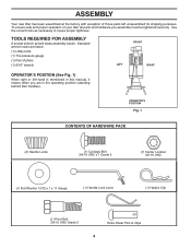
... x 1 x 11 Gauge (1) Handle Lock Lever (1) Hairpin Clip (1) Pivot Bolt 3/8-16 UNC Grade 5 Extra Shear Pins & Clips 4 TOOLS REQUIRED FOR ASSEMBLY A socket wrench set will make assembly easier. Standard wrench sizes are listed. (1) Utility knife (1) Tire pressure gauge (1) Pair of pliers (1) 9/16" wrench FRONT LEFT RIGHT OPERATOR'S POSITION (See Fig. 1) When right or left unassembled for shipping purposes. To ensure safe and proper operation of your tiller all parts and hardware...
... x 1 x 11 Gauge (1) Handle Lock Lever (1) Hairpin Clip (1) Pivot Bolt 3/8-16 UNC Grade 5 Extra Shear Pins & Clips 4 TOOLS REQUIRED FOR ASSEMBLY A socket wrench set will make assembly easier. Standard wrench sizes are listed. (1) Utility knife (1) Tire pressure gauge (1) Pair of pliers (1) 9/16" wrench FRONT LEFT RIGHT OPERATOR'S POSITION (See Fig. 1) When right or left unassembled for shipping purposes. To ensure safe and proper operation of your tiller all parts and hardware...

Owners Manual
Page 5
... ease handle assembly up " position. SIDE OF TILLER HANDLE ASSEMBLY GEARCASE NOTCH HANDLE LOCK • Grasp handle assembly. Tighten nut on L.H. GEARCASE SLOT HANDLE LOCK FLAT WASHER HANDLE LOCK LEVER CARRIAGE BOLT Fig. 3 handles_34 HANDLE BASE PIVOT BOLT LOCKNUT Fig. 5 5 IMPORTANT: WHEN UNPACKING AND ASSEMBLING TILLER, BE CAREFUL NOT TO STRETCH OR KINK CABLES. • While holding handle assembly, cut cable ties securing handle assembly to hold lever in place. • Insert second handle lock (with teeth inward) in front part of...
... ease handle assembly up " position. SIDE OF TILLER HANDLE ASSEMBLY GEARCASE NOTCH HANDLE LOCK • Grasp handle assembly. Tighten nut on L.H. GEARCASE SLOT HANDLE LOCK FLAT WASHER HANDLE LOCK LEVER CARRIAGE BOLT Fig. 3 handles_34 HANDLE BASE PIVOT BOLT LOCKNUT Fig. 5 5 IMPORTANT: WHEN UNPACKING AND ASSEMBLING TILLER, BE CAREFUL NOT TO STRETCH OR KINK CABLES. • While holding handle assembly, cut cable ties securing handle assembly to hold lever in place. • Insert second handle lock (with teeth inward) in front part of...
Owners Manual
Page 7
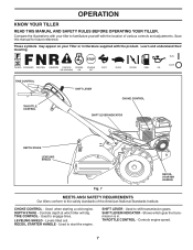
... at which gear the transmission is in literature supplied with the location of the American National Standards Institute. Controls engine speed. 7 RECOIL STARTER HANDLE - Used to engage tines. SHIFT LEVER INDICATOR - CHOKE CONTROL - Used when starting a cold engine. OPERATION KNOW YOUR TILLER READ THIS MANUAL AND SAFETY RULES BEFORE OPERATING YOUR TILLER. Levels tilled soil. Used to the safety standards of various controls and adjustments. TINE CONTROL THROTTLE CONTROL SHIFT LEVER CHOKE CONTROL SHIFT LEVER INDICATOR DEPTH STAKE LEVELING SHIELD RECOIL...
... at which gear the transmission is in literature supplied with the location of the American National Standards Institute. Controls engine speed. 7 RECOIL STARTER HANDLE - Used to engage tines. SHIFT LEVER INDICATOR - CHOKE CONTROL - Used when starting a cold engine. OPERATION KNOW YOUR TILLER READ THIS MANUAL AND SAFETY RULES BEFORE OPERATING YOUR TILLER. Levels tilled soil. Used to the safety standards of various controls and adjustments. TINE CONTROL THROTTLE CONTROL SHIFT LEVER CHOKE CONTROL SHIFT LEVER INDICATOR DEPTH STAKE LEVELING SHIELD RECOIL...

Owners Manual
Page 9
... tine control against the handle to desired speed. Acidic gas can attract moisture which leads to "RUN" position as engine warms up. AROUND THE YARD • Release the depth stake pin. USE CLEAN OIL AND FUEL AND STORE IN APPROVED, CLEAN, COVERED CONTAINERS. Drain the gas tank, start the engine and let it run out of an engine while in "FAST" position. • Turn fuel shut-off any source of ignition until engine reaches start tiller movement. BEFORE STARTING ENGINE...
... tine control against the handle to desired speed. Acidic gas can attract moisture which leads to "RUN" position as engine warms up. AROUND THE YARD • Release the depth stake pin. USE CLEAN OIL AND FUEL AND STORE IN APPROVED, CLEAN, COVERED CONTAINERS. Drain the gas tank, start the engine and let it run out of an engine while in "FAST" position. • Turn fuel shut-off any source of ignition until engine reaches start tiller movement. BEFORE STARTING ENGINE...
Owners Manual
Page 10
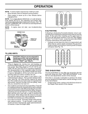
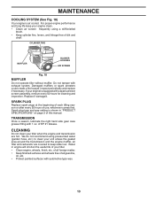
...;C), the carburetor fuel mixture may be adjusted for proper tilling. Then go back between passes. SPARK PLUG CHOKE CONTROL RECOIL STARTER engine_art_71 Fig. 12 THROTTLE CONTROL TILLING HINTS CAUTION: Until you , toward the row next to it may need to be advisable to till the soil at a speed which may contribute to excessive bounce and difficult handling of your tiller, start actual field use with shear pins (See "TINE REPLACEMENT...
...;C), the carburetor fuel mixture may be adjusted for proper tilling. Then go back between passes. SPARK PLUG CHOKE CONTROL RECOIL STARTER engine_art_71 Fig. 12 THROTTLE CONTROL TILLING HINTS CAUTION: Until you , toward the row next to it may need to be advisable to till the soil at a speed which may contribute to excessive bounce and difficult handling of your tiller, start actual field use with shear pins (See "TINE REPLACEMENT...
Owners Manual
Page 11
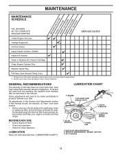
... Check Engine Oil Level Change Engine Oil Oil Pivot Points Inspect Spark Arrester / Muffler Inspect Air Screen Clean or Replace Air Cleaner Cartridge Clean Engine Cylinder Fins Replace Spark Plug 1,2 2 RH Gear Case Grease Fitting (1oz.) 1 - Change more often when operating in high ambient temperatures. 2 - A new spark plug and clean air filter assure proper airfuel mixture and help your tiller. BEFORE EACH USE • Check engine oil level. • Check tine operation. • Check for wear. All adjustments in this manual should replace the spark plug, clean or replace air...
... Check Engine Oil Level Change Engine Oil Oil Pivot Points Inspect Spark Arrester / Muffler Inspect Air Screen Clean or Replace Air Cleaner Cartridge Clean Engine Cylinder Fins Replace Spark Plug 1,2 2 RH Gear Case Grease Fitting (1oz.) 1 - Change more often when operating in high ambient temperatures. 2 - A new spark plug and clean air filter assure proper airfuel mixture and help your tiller. BEFORE EACH USE • Check engine oil level. • Check tine operation. • Check for wear. All adjustments in this manual should replace the spark plug, clean or replace air...
Owners Manual
Page 12
... of cover. • Remove air cleaner cover. • Carefully remove air cleaner cartridge. Do not allow dirt to avoid possible engine damage from tank before oil change. DO NOT USE PRESSURIZED AIR TO CLEAN OR DRY CARTRIDGE. MAINTENANCE Disconnect spark plug wire before starting the engine and after every 25 hours of operation or at least once a year if the tiller is not used for maintenance. Select the oil's SAE viscosity grade according to your engine oil level...
... of cover. • Remove air cleaner cover. • Carefully remove air cleaner cartridge. Do not allow dirt to avoid possible engine damage from tank before oil change. DO NOT USE PRESSURIZED AIR TO CLEAN OR DRY CARTRIDGE. MAINTENANCE Disconnect spark plug wire before starting the engine and after every 25 hours of operation or at least once a year if the tiller is not used for maintenance. Select the oil's SAE viscosity grade according to your engine oil level...
Owners Manual
Page 13
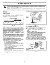
... FINS MUFFLER BLOWER HOUSING AIR SCREEN engine_art_71 Fig. 18 MUFFLER Do not operate tiller without muffler. We do not recommend using a stiff-bristled brush. • Keep cylinder fins, levers, and linkage free of all foreign matter. • Keep finished surfaces and wheels free of dirt and chaff. Water in "PRODUCT SPECIFICATIONS" on page 3 of your unit unless the gasket area around the transmission and the engine muffler, air filter and carburetor are...
... FINS MUFFLER BLOWER HOUSING AIR SCREEN engine_art_71 Fig. 18 MUFFLER Do not operate tiller without muffler. We do not recommend using a stiff-bristled brush. • Keep cylinder fins, levers, and linkage free of all foreign matter. • Keep finished surfaces and wheels free of dirt and chaff. Water in "PRODUCT SPECIFICATIONS" on page 3 of your unit unless the gasket area around the transmission and the engine muffler, air filter and carburetor are...

Owners Manual
Page 14
... pin from unit. • Replace belt guard by reversing above procedure. Pull wheel out from tiller about 1 inch. • Remove two (2) screws from side of belt guard. • Remove hex nut and washer from bottom of gasoline or oil which can be positioned at different settings between "HIGH" and "LOW" positions. • Retighten handle lock lever securely after adjusting. Handle height will pull to keep tiller from tipping. • Remove hairpin clip and clevis pin from spark plug and place wire...
... pin from unit. • Replace belt guard by reversing above procedure. Pull wheel out from tiller about 1 inch. • Remove two (2) screws from side of belt guard. • Remove hex nut and washer from bottom of gasoline or oil which can be positioned at different settings between "HIGH" and "LOW" positions. • Retighten handle lock lever securely after adjusting. Handle height will pull to keep tiller from tipping. • Remove hairpin clip and clevis pin from spark plug and place wire...
Owners Manual
Page 15
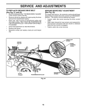
SERVICE AND ADJUSTMENTS TO REPLACE GROUND DRIVE BELT (See Fig. 21 and 22) • Remove belt guard (See "TO REMOVE BELT GUARD" in this section of this manual). • Remove old belt by slipping off engine pulley first then remove from transmission pulley. • Place new belt in "ENGAGED" position. NOTE POSITION OF BELT TO GUIDES. • Check belt adjustment as follows: • Loosen cable clip screw securing the drive control cable. • Slide cable forward for less tension and rearward for more tension until...
SERVICE AND ADJUSTMENTS TO REPLACE GROUND DRIVE BELT (See Fig. 21 and 22) • Remove belt guard (See "TO REMOVE BELT GUARD" in this section of this manual). • Remove old belt by slipping off engine pulley first then remove from transmission pulley. • Place new belt in "ENGAGED" position. NOTE POSITION OF BELT TO GUIDES. • Check belt adjustment as follows: • Loosen cable clip screw securing the drive control cable. • Slide cable forward for less tension and rearward for more tension until...
Owners Manual
Page 18
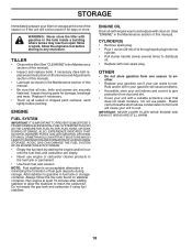
... the tiller with clean oil. (See "ENGINE" in the tank inside a building where fumes may reach an open flame or spark. ENGINE OIL Drain oil (with engine warm) and replace with gasoline in the Maintenance section of oil through spark plug hole into cylinder. • Pull starter handle slowly several times to rust. OTHER • Do not store gasoline from dust and dirt. • Cover your unit with new spark plug. IMPORTANT: NEVER COVER TILLER WHILE ENGINE...
... the tiller with clean oil. (See "ENGINE" in the tank inside a building where fumes may reach an open flame or spark. ENGINE OIL Drain oil (with engine warm) and replace with gasoline in the Maintenance section of oil through spark plug hole into cylinder. • Pull starter handle slowly several times to rust. OTHER • Do not store gasoline from dust and dirt. • Cover your unit with new spark plug. IMPORTANT: NEVER COVER TILLER WHILE ENGINE...
Owners Manual
Page 19
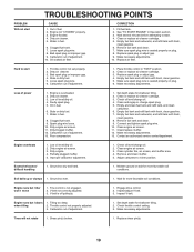
...fuel. 7. Spark plug wire loose. 10. Dirty engine air screen. 11. Dirty/clogged muffler. 12. Clean and regap or change oil. 4. Connect and tighten spark plug wire. 10. Partially plugged muffler. 5. Remove and clean muffler. 5. Tilling too deep. 2. Carburetor out of fuel. 2. Replace shear pin(s). 19 CORRECTION 1. Stale or dirty fuel. 5. Place throttle control in fuel. 8. Replace spark plug or adjust gap. 4. Make necessary adjustments. Loss of adjustment. 1. Engine is off pulley(s). 1. Faulty spark plug. 5. Check oil level/change spark plug...
...fuel. 7. Spark plug wire loose. 10. Dirty engine air screen. 11. Dirty/clogged muffler. 12. Clean and regap or change oil. 4. Connect and tighten spark plug wire. 10. Partially plugged muffler. 5. Remove and clean muffler. 5. Tilling too deep. 2. Carburetor out of fuel. 2. Replace shear pin(s). 19 CORRECTION 1. Stale or dirty fuel. 5. Place throttle control in fuel. 8. Replace spark plug or adjust gap. 4. Make necessary adjustments. Loss of adjustment. 1. Engine is off pulley(s). 1. Faulty spark plug. 5. Check oil level/change spark plug...

Parts Manual
Page 2
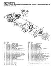
... 44 61-56 Handle 27 873 90 04-00 Nut, Hex Flange 1/4-20 unc 31 532 15 06-96 Bolt, Pivot 42 532 41 63-58 Screw #10 x .750 100 532 19 31-33 Control Asm. REPAIR PARTS TILLER - - DESCRIPTION 1 532 18 94-82 Throttle Control 2 532 42 76-43 Grip, Handle 6 532 44 60...06-08 Bolt, Carriage 3/8-16 x 1 Gr. 5 17 532 10 92-29 Lock, Handle 18 873 68 06-00 Nut, Crownlock 3/8-16 unc 19 819 13 16-11 Washer 13/32 x 1 x 11 Ga. 20 532 10 92-28 Lever, Lock, Handle 18 17 31 KEY PART NO. inches. 1 inch = 25.4 mm 2 MODEL NUMBER CRT900 (96093002100), PRODUCT NUMBER 960 93 00-21 HANDLE ASSEMBLY 6 ...
... 44 61-56 Handle 27 873 90 04-00 Nut, Hex Flange 1/4-20 unc 31 532 15 06-96 Bolt, Pivot 42 532 41 63-58 Screw #10 x .750 100 532 19 31-33 Control Asm. REPAIR PARTS TILLER - - DESCRIPTION 1 532 18 94-82 Throttle Control 2 532 42 76-43 Grip, Handle 6 532 44 60...06-08 Bolt, Carriage 3/8-16 x 1 Gr. 5 17 532 10 92-29 Lock, Handle 18 873 68 06-00 Nut, Crownlock 3/8-16 unc 19 819 13 16-11 Washer 13/32 x 1 x 11 Ga. 20 532 10 92-28 Lever, Lock, Handle 18 17 31 KEY PART NO. inches. 1 inch = 25.4 mm 2 MODEL NUMBER CRT900 (96093002100), PRODUCT NUMBER 960 93 00-21 HANDLE ASSEMBLY 6 ...
Parts Manual
Page 3
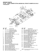
...00 Nut Lock Hex Flange 66 819 13 13-12 Washer 13/32 x 13/16 x 12 Ga. 67 874 76 05-24 Bolt, Hex 5/16-18 x 1-1/2 68 873 51 06-00 Nut, Keps Hex 3/8-16 unc 69 532 16 41-73 Keeper Belt Engine NOTE: All component dimensions given in U.S. MODEL NUMBER CRT900 (96093002100), PRODUCT NUMBER ...NO. inches. 1 inch = 25.4 mm 3 DESCRIPTION 3 873 22 06-00 Nut, Hex 3/8-16 4 532 43 24-20 Shield, Inner Belt Guard RT 5 532 16 43-29 Pin Spirol Flared 6 532 11 01-11 Lever, Shift 7 872 11 04-04 Bolt, Carriage 1/4-20 x 1/2 Gr. 5 8 532 00 87-00 Plate, Shift Indicator 9 532 08 67-77 Screw, Hex, Washer Head, ...
...00 Nut Lock Hex Flange 66 819 13 13-12 Washer 13/32 x 13/16 x 12 Ga. 67 874 76 05-24 Bolt, Hex 5/16-18 x 1-1/2 68 873 51 06-00 Nut, Keps Hex 3/8-16 unc 69 532 16 41-73 Keeper Belt Engine NOTE: All component dimensions given in U.S. MODEL NUMBER CRT900 (96093002100), PRODUCT NUMBER ...NO. inches. 1 inch = 25.4 mm 3 DESCRIPTION 3 873 22 06-00 Nut, Hex 3/8-16 4 532 43 24-20 Shield, Inner Belt Guard RT 5 532 16 43-29 Pin Spirol Flared 6 532 11 01-11 Lever, Shift 7 872 11 04-04 Bolt, Carriage 1/4-20 x 1/2 Gr. 5 8 532 00 87-00 Plate, Shift Indicator 9 532 08 67-77 Screw, Hex, Washer Head, ...
Parts Manual
Page 4
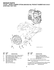
... Valve KEY PART NO. DESCRIPTION 15 Engine, Briggs & Stratton Model No. 12T402-0124-F8 (446492)(Order parts from Engine Manufacturer.) 44 873 51 06-00 Nut, Keps Hex 3/8-16 unc NOTE: All component dimensions given in U.S. NO. inches 1 inch = 25.4 mm For engine service and replacement parts, call the toll free number for your engine manufacturer listed below: Briggs & Stratton 1-800-233-3723 4 NO. REPAIR PARTS TILLER - - MODEL NUMBER CRT900 (96093002100), PRODUCT NUMBER...
... Valve KEY PART NO. DESCRIPTION 15 Engine, Briggs & Stratton Model No. 12T402-0124-F8 (446492)(Order parts from Engine Manufacturer.) 44 873 51 06-00 Nut, Keps Hex 3/8-16 unc NOTE: All component dimensions given in U.S. NO. inches 1 inch = 25.4 mm For engine service and replacement parts, call the toll free number for your engine manufacturer listed below: Briggs & Stratton 1-800-233-3723 4 NO. REPAIR PARTS TILLER - - MODEL NUMBER CRT900 (96093002100), PRODUCT NUMBER...
Parts Manual
Page 5
... 04-08 Screw 1/4-20 x 1/2 52 873 22 05-00 Nut, Hex 5/16-18 53 532 16 51-40 Kit, Bearing 58 532 17 95-20 Bolt Shoulder 1/4-20 unc x .875 60 532 18 32-26 Fitting Grease 62 532 43 10-15 Spacer - - 532 00 60-66 Grease, Plastilube #1 NOTE: All component dimensions given in U.S. REPAIR PARTS TILLER - - inches. 1 inch = 25...
... 04-08 Screw 1/4-20 x 1/2 52 873 22 05-00 Nut, Hex 5/16-18 53 532 16 51-40 Kit, Bearing 58 532 17 95-20 Bolt Shoulder 1/4-20 unc x .875 60 532 18 32-26 Fitting Grease 62 532 43 10-15 Spacer - - 532 00 60-66 Grease, Plastilube #1 NOTE: All component dimensions given in U.S. REPAIR PARTS TILLER - - inches. 1 inch = 25...
Parts Manual
Page 6
... Nut Lock Hex Flange 32 873 22 04-00 Nut Fin Hex 1/4-20 unc 33 810 04 04-00 Washer Lock Hvy Helical 1/4 35 872 11 05-05 Bolt 5/16-18 x 5/8 37 873 80 05-00 Nut Lock 5/16-18 unc 38 873 51 05-00 Nut, Keps Hex 5/16-18 unc NOTE: All component dimensions given in U.S. REPAIR PARTS TILLER - - inches. 1 inch...
... Nut Lock Hex Flange 32 873 22 04-00 Nut Fin Hex 1/4-20 unc 33 810 04 04-00 Washer Lock Hvy Helical 1/4 35 872 11 05-05 Bolt 5/16-18 x 5/8 37 873 80 05-00 Nut Lock 5/16-18 unc 38 873 51 05-00 Nut, Keps Hex 5/16-18 unc NOTE: All component dimensions given in U.S. REPAIR PARTS TILLER - - inches. 1 inch...
Parts Manual
Page 8
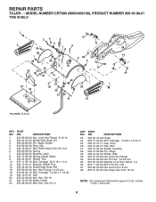
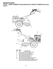
DESCRIPTION 532 42 91-96 Decal, Belt Guard Badge 532 44 23-04 Decal, Tine Shield 532 11 06-14 Decal, Hand Placement 532 10 21-80 Decal, Shift Indicator 532 42 29-72 Decal, Warning 532 43 22-78 Decal, Engine, AC 532 12 00-76 Decal, Warning, Rotating Tines 532 40 91-43 Decal, Engine, Fuel Tank 532 44 45-38 Operator's Manual (English/French) 532 44 45-39 Parts's Manual (English/French) 8 REPAIR PARTS TILLER - - MODEL NUMBER CRT900 (96093002100), PRODUCT NUMBER 960 93 00-21 DECALS 1 5 4 7 9 8 10 6 KEY NO. 1 4 5 6 7 8 9 10 - - - PART NO.
DESCRIPTION 532 42 91-96 Decal, Belt Guard Badge 532 44 23-04 Decal, Tine Shield 532 11 06-14 Decal, Hand Placement 532 10 21-80 Decal, Shift Indicator 532 42 29-72 Decal, Warning 532 43 22-78 Decal, Engine, AC 532 12 00-76 Decal, Warning, Rotating Tines 532 40 91-43 Decal, Engine, Fuel Tank 532 44 45-38 Operator's Manual (English/French) 532 44 45-39 Parts's Manual (English/French) 8 REPAIR PARTS TILLER - - MODEL NUMBER CRT900 (96093002100), PRODUCT NUMBER 960 93 00-21 DECALS 1 5 4 7 9 8 10 6 KEY NO. 1 4 5 6 7 8 9 10 - - - PART NO.


