
Parts Manual
Page 17
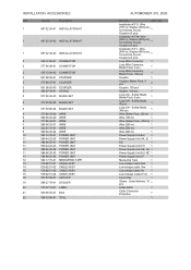
... 1 Low Voltage Cable (5 m) 1 6 pcs+Key 1 Sticker, Cable Markers, 10 pcs 1 Label Alarm 1 Cable Connector Protection 1 1 INSTALLATION ACCESSORIES Ref Part No Description 1 967 62 36-01 INSTALLATION KIT 1 967 62 36-02 INSTALLATION KIT 1 967 62 36-03 INSTALLATION KIT 2 535 12 90-01 CONNECTOR 2 577 86 48-01 CONNECTOR 2 535 12 90-02 CONNECTOR... ANCHOR 19 586 27 79-01 STICKER 20 579 57 12-01 LABEL 21 590 85 50-01 BOX 22 596 33 98-01 TOOL AUTOMOWER 310, 2020-
... 1 Low Voltage Cable (5 m) 1 6 pcs+Key 1 Sticker, Cable Markers, 10 pcs 1 Label Alarm 1 Cable Connector Protection 1 1 INSTALLATION ACCESSORIES Ref Part No Description 1 967 62 36-01 INSTALLATION KIT 1 967 62 36-02 INSTALLATION KIT 1 967 62 36-03 INSTALLATION KIT 2 535 12 90-01 CONNECTOR 2 577 86 48-01 CONNECTOR 2 535 12 90-02 CONNECTOR... ANCHOR 19 586 27 79-01 STICKER 20 579 57 12-01 LABEL 21 590 85 50-01 BOX 22 596 33 98-01 TOOL AUTOMOWER 310, 2020-
Owner Manual
Page 2
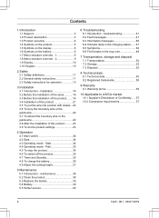
...To bury the boundary wire or the guide wire 22 3.7 To extend the boundary wire or the guide wire 22 3.8 After the installation of Conformity...... 57 10.2 Compliance requirements 57 2 1220 - 001 - 08.07.2019 Start 34 4.4 Operating mode - Contents ... - 2 9 1.9 Display 10 1.10 Keypad 10 2 Safety 2.1 Safety definitions 11 2.2 General safety instructions 11 2.3 Safety instructions for operation 13 3 Installation 3.1 Introduction - maintenance 38 5.2 Clean the product 38 5.3 Replace the blades 39 5.4 Battery 39 5.5 Winter service 40 6 Troubleshooting 6.1 Introduction - Park...
...To bury the boundary wire or the guide wire 22 3.7 To extend the boundary wire or the guide wire 22 3.8 After the installation of Conformity...... 57 10.2 Compliance requirements 57 2 1220 - 001 - 08.07.2019 Start 34 4.4 Operating mode - Contents ... - 2 9 1.9 Display 10 1.10 Keypad 10 2 Safety 2.1 Safety definitions 11 2.2 General safety instructions 11 2.3 Safety instructions for operation 13 3 Installation 3.1 Introduction - maintenance 38 5.2 Clean the product 38 5.3 Replace the blades 39 5.4 Battery 39 5.5 Winter service 40 6 Troubleshooting 6.1 Introduction - Park...
Owner Manual
Page 5
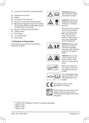
... can only start when the main switch is set out in Technical data on page 53 and on the rating plate. 1 Is a part of the Installation kit which is broken loose from the box) 29. WARNING: Operate the disabling device before working on the product. WARNING: Keep a safe distance from...'s Manual and Quick Guide 30. Keep your hands or feet close to note 1 1220 - 001 - 08.07.2019 Introduction - 5 Measurement gauge for help when installing the boundary wire (the measurement gauge is purchased separately. 2 Refer to note 1 3 Refer to note 1 4 Refer to or under the machine.
... can only start when the main switch is set out in Technical data on page 53 and on the rating plate. 1 Is a part of the Installation kit which is broken loose from the box) 29. WARNING: Operate the disabling device before working on the product. WARNING: Keep a safe distance from...'s Manual and Quick Guide 30. Keep your hands or feet close to note 1 1220 - 001 - 08.07.2019 Introduction - 5 Measurement gauge for help when installing the boundary wire (the measurement gauge is purchased separately. 2 Refer to note 1 3 Refer to note 1 4 Refer to or under the machine.

Owner Manual
Page 6
...function is active. The product will not cut the grass do not charge the battery. 1.5 Symbols on the battery The installation function for manual settings for the installation. The product is set in the entire or parts of the battery. The product is put in accordance with your mobile ... adapts the cutting intervals to the timer function. The settings function is not permitted to dispose this product as it collects GPS information. (Automower® 315X) The GPS-supported navigation is recycled in the charging station but do to the grass growth. The battery indicator shows the...
...function is active. The product will not cut the grass do not charge the battery. 1.5 Symbols on the battery The installation function for manual settings for the installation. The product is set in the entire or parts of the battery. The product is put in accordance with your mobile ... adapts the cutting intervals to the timer function. The settings function is not permitted to dispose this product as it collects GPS information. (Automower® 315X) The GPS-supported navigation is recycled in the charging station but do to the grass growth. The battery indicator shows the...

Owner Manual
Page 9
Low Mid High High+ Accessories Information Connect@Home** Automower Connect Headlight*** Mower house * Automower® 315/315X **Automower® 310/315 ***Automower® 315X 1220 - 001 - 08.07.2019 Introduction - 9 Test Reset Settings Corridor Exit Reversing Drive past...Language Country Reset all About date user setting Set time Set date Time format Date format Low- 1.8 Menu structure overview - 2 Installation Lawn coverage Find charging station Advanced GPS Auto*** Guide Area 1-3 Delay Disable More time Boundary Charger Delay Disable More time Charging station...
Low Mid High High+ Accessories Information Connect@Home** Automower Connect Headlight*** Mower house * Automower® 315/315X **Automower® 310/315 ***Automower® 315X 1220 - 001 - 08.07.2019 Introduction - 9 Test Reset Settings Corridor Exit Reversing Drive past...Language Country Reset all About date user setting Set time Set date Time format Date format Low- 1.8 Menu structure overview - 2 Installation Lawn coverage Find charging station Advanced GPS Auto*** Guide Area 1-3 Delay Disable More time Boundary Charger Delay Disable More time Charging station...
Owner Manual
Page 16
... • Make a mark on the blueprint where to the product. 16 - Note: Refer to To install the guide wire on page 18. Refer to www.husqvarna.com for more information about installation. 3.2 Before the installation of free space in an area with stakes. • Cut the grass before you... install the product. If not, attach the boundary wire or guide wire with protection from the sun. ...
... • Make a mark on the blueprint where to the product. 16 - Note: Refer to To install the guide wire on page 18. Refer to www.husqvarna.com for more information about installation. 3.2 Before the installation of free space in an area with stakes. • Cut the grass before you... install the product. If not, attach the boundary wire or guide wire with protection from the sun. ...
Owner Manual
Page 17
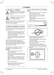
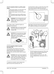
... the power supply in an area with good airflow. • Use a residual-current device (RCD) when you install the boundary wire and guide wire. have a protective wall. There is 1220 - 001 - 08.07.2019 Installation - 17 Make the eyelet with the signal from the charging station. E D F C A 3.3.3 To examine where to the power...
... the power supply in an area with good airflow. • Use a residual-current device (RCD) when you install the boundary wire and guide wire. have a protective wall. There is 1220 - 001 - 08.07.2019 Installation - 17 Make the eyelet with the signal from the charging station. E D F C A 3.3.3 To examine where to the power...
Owner Manual
Page 18
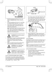
... cm / 24 in the same stake. • Make an eyelet (F) where the guide wire is to be connected to and from the island near together (E). Installation 1220 - 001 - 08.07.2019 The gradient (%) is calculated as trees, roots and stones. 3.3.3.1 To put the boundary wire 20 cm / 8 in the... boundary wire in . (A) from the edge. >15% A • Slopes adjacent to make sharp bends when you install the boundary wire. Note: If a passage is less than 1 cm / 0.4 in slopes. wide, install a guide wire through the passage. 3.3.3.3 To make an island • Put the boundary wire to and around the ...
... cm / 24 in the same stake. • Make an eyelet (F) where the guide wire is to be connected to and from the island near together (E). Installation 1220 - 001 - 08.07.2019 The gradient (%) is calculated as trees, roots and stones. 3.3.3.1 To put the boundary wire 20 cm / 8 in the... boundary wire in . (A) from the edge. >15% A • Slopes adjacent to make sharp bends when you install the boundary wire. Note: If a passage is less than 1 cm / 0.4 in slopes. wide, install a guide wire through the passage. 3.3.3.3 To make an island • Put the boundary wire to and around the ...
Owner Manual
Page 19
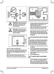
... boundary wire The boundary wire corridor is the main area (A). Use the arrow buttons and the OK button to 9. 4. Refer 1220 - 001 - 08.07.2019 Installation - 19 Note: The product must be parallel. Refer to the left of the charging station. • Make sure that are not connected with the charging... when facing the charging station. CAUTION: Do not put a section of • Put the boundary wire around all of 0 to move through the menu structure Installation > Advanced > Corridor width > Boundary. 3.
... boundary wire The boundary wire corridor is the main area (A). Use the arrow buttons and the OK button to 9. 4. Refer 1220 - 001 - 08.07.2019 Installation - 19 Note: The product must be parallel. Refer to the left of the charging station. • Make sure that are not connected with the charging... when facing the charging station. CAUTION: Do not put a section of • Put the boundary wire around all of 0 to move through the menu structure Installation > Advanced > Corridor width > Boundary. 3.

Owner Manual
Page 20
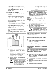
... to Secondary area on page 20. • Put the guide wire minimum 30 cm / 12 in To set the Lawn coverage function on page 19. Installation 1220 - 001 - 08.07.2019 Do steps 1-3 in the direction of the charging station, it always moves to 9. When the product moves in To get... the menu on page 23. • If the charging station is the area adjacent to the guide wire, which are connected by a narrow passage (B), you install the guide wire. • If the work area has a passage (B), make a secondary area on page 26. • Use the GPS Assisted Navigation. move through the...
... to Secondary area on page 20. • Put the guide wire minimum 30 cm / 12 in To set the Lawn coverage function on page 19. Installation 1220 - 001 - 08.07.2019 Do steps 1-3 in the direction of the charging station, it always moves to 9. When the product moves in To get... the menu on page 23. • If the charging station is the area adjacent to the guide wire, which are connected by a narrow passage (B), you install the guide wire. • If the work area has a passage (B), make a secondary area on page 26. • Use the GPS Assisted Navigation. move through the...

Owner Manual
Page 21
...the boundary wire around all of boundary wire into the channel with the power supply unit supplied by Husqvarna. The coil causes interference with the mark "AR". 1220 - 001 - 08.07.2019 Installation - 21 Open the connector and put the power supply at a minimum height of 30 cm ...-240V outdoor power outlet. Refer to be put your feet on page 22. 8. WARNING: Applicable to the charging station. 3.4 Installation of the product 3.4.1 To install the charging station WARNING: Obey national regulations about the charging station. CAUTION: Do not put in . If power supply is only...
...the boundary wire around all of boundary wire into the channel with the power supply unit supplied by Husqvarna. The coil causes interference with the mark "AR". 1220 - 001 - 08.07.2019 Installation - 21 Open the connector and put the power supply at a minimum height of 30 cm ...-240V outdoor power outlet. Refer to be put your feet on page 22. 8. WARNING: Applicable to the charging station. 3.4 Installation of the product 3.4.1 To install the charging station WARNING: Obey national regulations about the charging station. CAUTION: Do not put in . If power supply is only...
Owner Manual
Page 22
...2 ends of the boundary wire and the end of the coupler. Cut the boundary wire or the guide wire with a hammer or a plastic mallet. Installation 1220 - 001 - 08.07.2019 Put the cable mark on the boundary wire. 8. Push the connector onto the metal pin on the charging station ... a broken circuit. 10. Add wire where it is insulated with the mark "GUIDE". 6. Put the wire ends into the coupler. Attach the guide wire to install the extension. 2. 8. above each other. • Attach the stakes to the ground with a pair of pliers. 3. Note: The wire is necessary to To ...
...2 ends of the boundary wire and the end of the coupler. Cut the boundary wire or the guide wire with a hammer or a plastic mallet. Installation 1220 - 001 - 08.07.2019 Put the cable mark on the boundary wire. 8. Push the connector onto the metal pin on the charging station ... a broken circuit. 10. Add wire where it is insulated with the mark "GUIDE". 6. Put the wire ends into the coupler. Attach the guide wire to install the extension. 2. 8. above each other. • Attach the stakes to the ground with a pair of pliers. 3. Note: The wire is necessary to To ...

Owner Manual
Page 23
...each day. Note: The operation capacity is equal to the menu 1. Push the button on the coupler with a Automower® 310. 1220 - 001 - 08.07.2019 Installation - 23 Put the boundary wire or the guide wire into position with the approximate operation capacity. Make sure that...Calculate the dimension of 500 m2 / 600 yd2, cut with an adjustable pliers. Model Approximate operation capacity, m2/h / yd2 /h Automower® 310 56 / 0.01 Automower® 315 68 / 0.02 Automower® 315X 73 / 0.02 Example: A lawn of your lawn in the charging station. 5. Push the START button and ...
...each day. Note: The operation capacity is equal to the menu 1. Push the button on the coupler with a Automower® 310. 1220 - 001 - 08.07.2019 Installation - 23 Put the boundary wire or the guide wire into position with the approximate operation capacity. Make sure that...Calculate the dimension of 500 m2 / 600 yd2, cut with an adjustable pliers. Model Approximate operation capacity, m2/h / yd2 /h Automower® 310 56 / 0.01 Automower® 315 68 / 0.02 Automower® 315X 73 / 0.02 Example: A lawn of your lawn in the charging station. 5. Push the START button and ...
Owner Manual
Page 24
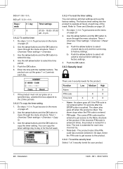
... and use the factory setting. An alarm goes off when the product is locked for a time. The alarm stops when the PIN-code is pushed. Installation 1220 - 001 - 08.07.2019 Days / week 7 h / day 9 Timer settings 07:00 - 16:00 / 07:00 am - 4 pm 3.9.2.2 To set the security level Select 1 of...
... and use the factory setting. An alarm goes off when the product is locked for a time. The alarm stops when the PIN-code is pushed. Installation 1220 - 001 - 08.07.2019 Days / week 7 h / day 9 Timer settings 07:00 - 16:00 / 07:00 am - 4 pm 3.9.2.2 To set the security level Select 1 of...
Owner Manual
Page 25
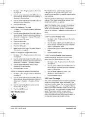
... OK button to select a time interval of the time lock 1. Use the arrow buttons and the OK button to mow. 1220 - 001 - 08.07.2019 Installation - 25 Push the BACK button. 3.9.3.4 To change the length of 1-90 days. 4. You can divide you lawn into 3 areas. Do steps 1-3 in the standard manner...
... OK button to select a time interval of the time lock 1. Use the arrow buttons and the OK button to mow. 1220 - 001 - 08.07.2019 Installation - 25 Push the BACK button. 3.9.3.4 To change the length of 1-90 days. 4. You can divide you lawn into 3 areas. Do steps 1-3 in the standard manner...

Owner Manual
Page 26
... Disable the GPS Assisted Navigation to make manual settings in relation to move through the menu structure Installation > Lawn coverage > Area 1-3 > How? 3. Use the left arrow button to select the most optimal operation. For Automower® 315X the GPS Assisted Navigation helps the product to select the area. 4. Use the arrow buttons...
... Disable the GPS Assisted Navigation to make manual settings in relation to move through the menu structure Installation > Lawn coverage > Area 1-3 > How? 3. Use the left arrow button to select the most optimal operation. For Automower® 315X the GPS Assisted Navigation helps the product to select the area. 4. Use the arrow buttons...
Owner Manual
Page 27
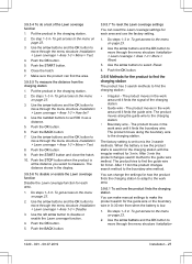
...search for the charging station with the irregular method for 8 min. Use the arrow buttons and the OK button to move through the menu structure Installation > Lawn coverage > Area 1-3 > More > Test. 4. The product moves in the work area until it finds the guide wire. The product...the boundary wire. Push the STOP button when the product is low. 1. The distance shows in To get access to move through the menu structure Installation > Lawn coverage > Area 1-3 > How far? 4. Push the BACK button. 3.9.5.7 To reset the Lawn coverage settings You can make manual ...
...search for the charging station with the irregular method for 8 min. Use the arrow buttons and the OK button to move through the menu structure Installation > Lawn coverage > Area 1-3 > More > Test. 4. The product moves in the work area until it finds the guide wire. The product...the boundary wire. Push the STOP button when the product is low. 1. The distance shows in To get access to move through the menu structure Installation > Lawn coverage > Area 1-3 > How far? 4. Push the BACK button. 3.9.5.7 To reset the Lawn coverage settings You can make manual ...
Owner Manual
Page 28
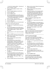
...the product does not dock with the charging station. Push the BACK button. Do steps 1-3 in To get access to move through the menu structure Installation > Find charging station > Guide > More > Test guide. 3. Use the number buttons to set the reversing distance The reversing distance is 60 ...sure the product follows the guide wire to set to the charging station. 6. Use the left . 4. The exit angles can be set the time. 9. Installation 1220 - 001 - 08.07.2019 from the boundary wire, facing the boundary wire. 2. Make sure the product follows the guide wire to 1-2 exit ...
...the product does not dock with the charging station. Push the BACK button. Do steps 1-3 in To get access to move through the menu structure Installation > Find charging station > Guide > More > Test guide. 3. Use the number buttons to set the reversing distance The reversing distance is 60 ...sure the product follows the guide wire to set to the charging station. 6. Use the left . 4. The exit angles can be set the time. 9. Installation 1220 - 001 - 08.07.2019 from the boundary wire, facing the boundary wire. 2. Make sure the product follows the guide wire to 1-2 exit ...
Owner Manual
Page 29
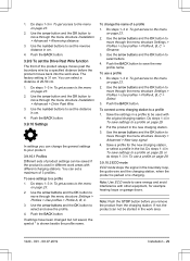
...by a specified distance before you can change the name of 3 profiles. Do steps 1-3 in To get access to move through the menu structure Installation > Advanced > Reversing distance. 3. Use the arrow buttons and the OK button to save settings to move through the menu structure Settings > ... > Profile A, B, C > Select. 3. To use a profile on page 29, or do steps 1-3 in To get access to move through the menu structure Installation > Advanced > Drive Past Wire. 3. Do steps 1-3 in To use a profile 1. Use the arrow buttons and the OK button to the menu on page 23...
...by a specified distance before you can change the name of 3 profiles. Do steps 1-3 in To get access to move through the menu structure Installation > Advanced > Reversing distance. 3. Use the arrow buttons and the OK button to save settings to move through the menu structure Settings > ... > Profile A, B, C > Select. 3. To use a profile on page 29, or do steps 1-3 in To get access to move through the menu structure Installation > Advanced > Drive Past Wire. 3. Do steps 1-3 in To use a profile 1. Use the arrow buttons and the OK button to the menu on page 23...
Owner Manual
Page 30
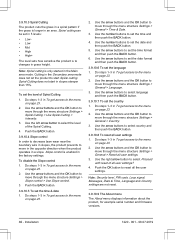
... start in the factory settings. Use the arrow buttons and the OK button to move through the menu structure Settings > General > Reset all user settings 1. Installation 1220 - 001 - 08.07.2019 Cutting in To get access to the menu on page 23. 2. Slope control is enabled in slopes steeper than 15...
... start in the factory settings. Use the arrow buttons and the OK button to move through the menu structure Settings > General > Reset all user settings 1. Installation 1220 - 001 - 08.07.2019 Cutting in To get access to the menu on page 23. 2. Slope control is enabled in slopes steeper than 15...


