
Owners Manual
Page 1
Models: AR19/968982102 AR19B/968999277 AR19B/968999358 AR19H/968999363 AR25H/968981104 AR25/968982105 MANUAL NO. 540200239 REV. 02 (11/30/05) Operators manual Please read these instructions carefully and make sure you understand them before using the machine.
Models: AR19/968982102 AR19B/968999277 AR19B/968999358 AR19H/968999363 AR25H/968981104 AR25/968982105 MANUAL NO. 540200239 REV. 02 (11/30/05) Operators manual Please read these instructions carefully and make sure you understand them before using the machine.
Owners Manual
Page 2
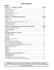
... You Start...10 Aerating ...10 Throttle Adjustment (Model AR25 Honda engine only 11 Rear Wheel Adjustment ...12 Turning and Maneuvering...12 Operating on Hills ...12 Section 3 · Maintenance and Service Instructions Page Transporting the Husqvarna Aerator 13 Cleaning and Washing ...13 Two-Minute Warning ...13 Storage ...13 Preventative Maintenance Schedule Inspection Schedule ...14 Lubrication Schedule ...14 Tine Wear ...14 Service Engine Service & Maintenance 14 Drive Train Engine Removal and Replacement 15 Drive Belt Replacement and Adjustment 15 Clutch Cable Removal...
... You Start...10 Aerating ...10 Throttle Adjustment (Model AR25 Honda engine only 11 Rear Wheel Adjustment ...12 Turning and Maneuvering...12 Operating on Hills ...12 Section 3 · Maintenance and Service Instructions Page Transporting the Husqvarna Aerator 13 Cleaning and Washing ...13 Two-Minute Warning ...13 Storage ...13 Preventative Maintenance Schedule Inspection Schedule ...14 Lubrication Schedule ...14 Tine Wear ...14 Service Engine Service & Maintenance 14 Drive Train Engine Removal and Replacement 15 Drive Belt Replacement and Adjustment 15 Clutch Cable Removal...
Owners Manual
Page 3
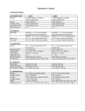
Operator's Guide SPECIFICATIONS A) POWER UNIT Engine Clutch Primary drive Secondary drive Gear reduction AR19 3.5HP Briggs I/C (2.6kw) 4HP Honda (3kw) Belt tensioner One V-belt (A-44") Permalube Chain 6:1 AR25 3.5HP Briggs l/C (2.6kw) 4HP Honda (3kw) Belt tensioner One V-belt (A-44") Permalube Chain 6:1 B) WHEELS Bearings Rear tires Front tire FRONT - ¾" (1.9 cm) sealed ball bearings with stamping kit...hr (3716 m2/h) D) WEIGHTS Net weight Shipping weight Removable weights 288 Ibs (131 kg) 355 Ibs (161..." (94cm) w/ handle folded 51.5 (130.8cm) 39.5 (100.3cm) w/ handle folded 57.5 (146...
Operator's Guide SPECIFICATIONS A) POWER UNIT Engine Clutch Primary drive Secondary drive Gear reduction AR19 3.5HP Briggs I/C (2.6kw) 4HP Honda (3kw) Belt tensioner One V-belt (A-44") Permalube Chain 6:1 AR25 3.5HP Briggs l/C (2.6kw) 4HP Honda (3kw) Belt tensioner One V-belt (A-44") Permalube Chain 6:1 B) WHEELS Bearings Rear tires Front tire FRONT - ¾" (1.9 cm) sealed ball bearings with stamping kit...hr (3716 m2/h) D) WEIGHTS Net weight Shipping weight Removable weights 288 Ibs (131 kg) 355 Ibs (161..." (94cm) w/ handle folded 51.5 (130.8cm) 39.5 (100.3cm) w/ handle folded 57.5 (146...
Owners Manual
Page 6
... moving or rotating parts. • Do not lift Model AR19. • Do not lift Model AR25. • Do not run engine while servicing. • Do not use on slopes exceeding 35% grade. • Do not place hands or feet near moving the equipment. • Make sure all maintenance and service instructions before attempting work. • Read engine manufacturer's operating and maintenance instructions. • Remove spark plug wire before attempting...
... moving or rotating parts. • Do not lift Model AR19. • Do not lift Model AR25. • Do not run engine while servicing. • Do not use on slopes exceeding 35% grade. • Do not place hands or feet near moving the equipment. • Make sure all maintenance and service instructions before attempting work. • Read engine manufacturer's operating and maintenance instructions. • Remove spark plug wire before attempting...
Owners Manual
Page 7
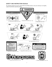
SAFETY AND INSTRUCTION DECALS The following decals are missing or not legible, replace them before operating aerator. Model AR25 only (1 ea) I - Model AR25 only (1 ea) E - Model AR19 & AR25 only (1 ea) 7 K - Model AR25 only (2 ea) D1 - Model AR19 only (1 ea) D2 - Model AR19 & AR25 only (1 ea) H - Model AR19 & AR25 only (1 ea) A - Model AR19 & AR25 only (2 ea) C - Model AR19 & AR25 only (1 ea) G - Model AR19 & AR25 only (1 ea) B - If any are found on Model AR19 and AR25 aerators. Model AR19 & AR25 only (1 ea) F - Model AR19 only (1 ea) J -
SAFETY AND INSTRUCTION DECALS The following decals are missing or not legible, replace them before operating aerator. Model AR25 only (1 ea) I - Model AR25 only (1 ea) E - Model AR19 & AR25 only (1 ea) 7 K - Model AR25 only (2 ea) D1 - Model AR19 only (1 ea) D2 - Model AR19 & AR25 only (1 ea) H - Model AR19 & AR25 only (1 ea) A - Model AR19 & AR25 only (2 ea) C - Model AR19 & AR25 only (1 ea) G - Model AR19 & AR25 only (1 ea) B - If any are found on Model AR19 and AR25 aerators. Model AR19 & AR25 only (1 ea) F - Model AR19 only (1 ea) J -
Owners Manual
Page 8
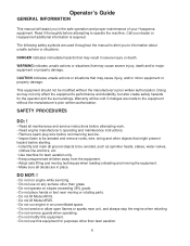
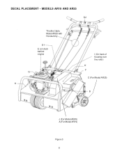
MODELS AR19 AND AR25 D2 Throttle Cable Model AR25 with Honda Only D1 E (on deck behind engine G H I (On back of housing over tine rotor) K F C (For Model AR25) B J (For Model AR25) A (For Model AR19) Figure 3 8 DECAL PLACEMENT -
MODELS AR19 AND AR25 D2 Throttle Cable Model AR25 with Honda Only D1 E (on deck behind engine G H I (On back of housing over tine rotor) K F C (For Model AR25) B J (For Model AR25) A (For Model AR19) Figure 3 8 DECAL PLACEMENT -
Owners Manual
Page 9
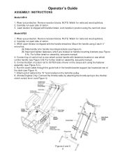
.... 3. Operator's Guide ASSEMBLY INSTRUCTIONS Model AR19 1. Carefully cut open side of cable to the throttle/ clutch control lever. (see parts manual. 4. Model AR25 1. Wear eye protection. For further detail on handle mounting brackets (see Figure 4). 7. Lawn Aerator is shipped with handle folded. Carefully cut open side of the deck (see Figure 5-A). Mount the handle using the cam lock lever. Lock handle in the handle bracket support bar located at rear of carton. 3. Remove wooden blocks. Run the clutch cable through the guide hole in position using 2 each...
.... 3. Operator's Guide ASSEMBLY INSTRUCTIONS Model AR19 1. Carefully cut open side of cable to the throttle/ clutch control lever. (see parts manual. 4. Model AR25 1. Wear eye protection. For further detail on handle mounting brackets (see Figure 4). 7. Lawn Aerator is shipped with handle folded. Carefully cut open side of the deck (see Figure 5-A). Mount the handle using the cam lock lever. Lock handle in the handle bracket support bar located at rear of carton. 3. Remove wooden blocks. Run the clutch cable through the guide hole in position using 2 each...
Owners Manual
Page 10
... mounted. Be sure handle is level when filling with little effort. To stop, release clutch control. When should be pulled up (to 3 inches with oil. 2. Rear wheel control handle must be able to drive the tool in its operating position, lock the handle cam lock (Model AR19 only). 3. Soil conditions will determine whether it is necessary to engine manual). BEFORE YOU START 1. AR25 Honda Engines Only: The throttle cable has been installed by raising the rear...
... mounted. Be sure handle is level when filling with little effort. To stop, release clutch control. When should be pulled up (to 3 inches with oil. 2. Rear wheel control handle must be able to drive the tool in its operating position, lock the handle cam lock (Model AR19 only). 3. Soil conditions will determine whether it is necessary to engine manual). BEFORE YOU START 1. AR25 Honda Engines Only: The throttle cable has been installed by raising the rear...
Owners Manual
Page 11
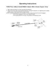
Tightening will increase engine speed, loosening will stall. • If the engine speed is too high, the gradual controlled start is lost. 11 Model AR25 (Honda Engine Only) 1. NOTE: A properly adjusted throttle will slightly increase engine speed as the clutch engages. • If the clutch engages too soon, the engine will reduce engine speed. Adjust the throttle cable at the adjuster bracket by turning the adjuster nut. Start engine and allow it to reach operating temperature. 2. Operating Instructions THROTTLE CABLE ADJUSTMENT.
Tightening will increase engine speed, loosening will stall. • If the engine speed is too high, the gradual controlled start is lost. 11 Model AR25 (Honda Engine Only) 1. NOTE: A properly adjusted throttle will slightly increase engine speed as the clutch engages. • If the clutch engages too soon, the engine will reduce engine speed. Adjust the throttle cable at the adjuster bracket by turning the adjuster nut. Start engine and allow it to reach operating temperature. 2. Operating Instructions THROTTLE CABLE ADJUSTMENT.
Owners Manual
Page 12
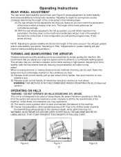
NOTE: Adjusting for a comfortable walking speed. We recommend that when operating on the tines. This unit is not designed to be controlled accordingly. (B) With the rear wheels adjusted to the full up position, you face: (A) Release clutch control handle, pull up rear wheel control handle, then pivot machine on rear wheels to turn. (B) Release clutch control handle, lift handle bar and pivot machine on steep slopes. Operating Instructions REAR WHEEL ADJUSTMENT The rear wheel depth/stability control knob (see...
NOTE: Adjusting for a comfortable walking speed. We recommend that when operating on the tines. This unit is not designed to be controlled accordingly. (B) With the rear wheels adjusted to the full up position, you face: (A) Release clutch control handle, pull up rear wheel control handle, then pivot machine on rear wheels to turn. (B) Release clutch control handle, lift handle bar and pivot machine on steep slopes. Operating Instructions REAR WHEEL ADJUSTMENT The rear wheel depth/stability control knob (see...
Owners Manual
Page 13
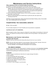
... WHEN TRAVELLING UP OR DOWN HILL. Engine damage may result from downhill side to set the rear wheels for extra stability. Handle may be tipped on their engine guard for cleaning and access for engine storage information. 2 Clean machine. 3. ONLY DISENGAGE ON FLAT SURFACE. Use engine power to run the aerator across a hill. See engine manufacturers operating and maintenance instructions. STORAGE 1. Cover all scratches with machine in place...
... WHEN TRAVELLING UP OR DOWN HILL. Engine damage may result from downhill side to set the rear wheels for extra stability. Handle may be tipped on their engine guard for cleaning and access for engine storage information. 2 Clean machine. 3. ONLY DISENGAGE ON FLAT SURFACE. Use engine power to run the aerator across a hill. See engine manufacturers operating and maintenance instructions. STORAGE 1. Cover all scratches with machine in place...
Owners Manual
Page 14
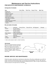
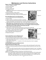
... performance will wear. Inspect tines using the drawing, replace when at minimum length or before. (Tines are 5" when new.) ENGINE SERVICE AND MAINTENANCE Follow the engine manufacturers maintenance instructions. Maintenance and Service Instructions PREVENTATIVE MAINTENANCE SCHEDULE A) Inspection Schedule Item • Engine Oil • Gear box oil • Engine air cleaner • Clutch & cable • Chain tension • Belt wear & tension • Tine wear & condition • Fasteners • Sprockets & set screws • Frame condition • Decals...
... performance will wear. Inspect tines using the drawing, replace when at minimum length or before. (Tines are 5" when new.) ENGINE SERVICE AND MAINTENANCE Follow the engine manufacturers maintenance instructions. Maintenance and Service Instructions PREVENTATIVE MAINTENANCE SCHEDULE A) Inspection Schedule Item • Engine Oil • Gear box oil • Engine air cleaner • Clutch & cable • Chain tension • Belt wear & tension • Tine wear & condition • Fasteners • Sprockets & set screws • Frame condition • Decals...
Owners Manual
Page 15
... cable adjustment. 4 Attach the new adjuster bracket to the S hook. 4. Remove weights for Husqvarna to give many hours of the housing. 3. Attach clutch cable to the bracket on the spring on the idler assembly, then connect opposite end of housing. 3. If engine speed is only an approximate setting, some additional adjustment may be lost. 15 Maintenance and Service Instructions Engine, Removal and Replacement 1. Figure 14 Clutch Cable Removal and Replacement 1.Turn off engine and remove the drive guard cover. 2. Remove the old throttle cable and route the new cable...
... cable adjustment. 4 Attach the new adjuster bracket to the S hook. 4. Remove weights for Husqvarna to give many hours of the housing. 3. Attach clutch cable to the bracket on the spring on the idler assembly, then connect opposite end of housing. 3. If engine speed is only an approximate setting, some additional adjustment may be lost. 15 Maintenance and Service Instructions Engine, Removal and Replacement 1. Figure 14 Clutch Cable Removal and Replacement 1.Turn off engine and remove the drive guard cover. 2. Remove the old throttle cable and route the new cable...
Owners Manual
Page 16
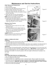
... grease on adjustment screw to let the aerator rest on outboard side. Remove weights and drive guard. 3. Turn off engine and empty all fuel from top (drive sprocket side) and route in the operating position, slowly tighten the cam rod lock nut (1/4 turn at the center point between the wheel sprocket and the rotor sprocket (see Figure 16). MODEL AR19 ONLY Inspection 1. WHEELS Drive Wheel Shaft Removal and Replacement 1. Install master link with pin plate on engine...
... grease on adjustment screw to let the aerator rest on outboard side. Remove weights and drive guard. 3. Turn off engine and empty all fuel from top (drive sprocket side) and route in the operating position, slowly tighten the cam rod lock nut (1/4 turn at the center point between the wheel sprocket and the rotor sprocket (see Figure 16). MODEL AR19 ONLY Inspection 1. WHEELS Drive Wheel Shaft Removal and Replacement 1. Install master link with pin plate on engine...
Owners Manual
Page 17
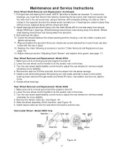
... Service Instructions Drive Wheel Shaft Removal and Replacement (Continued) 7. Install bearings and sprocket loosely onto the shaft. Wheel shaft bearing should have hub facing away from sprocket. 9. Align and tighten the sprocket (there are rusted in place and tighten set screw and, using a hammer, with seals carefully in place. 12. Make sure unit is on level ground and engine is shut off. 2. Turn the rear wheel depth/stability control knob...
... Service Instructions Drive Wheel Shaft Removal and Replacement (Continued) 7. Install bearings and sprocket loosely onto the shaft. Wheel shaft bearing should have hub facing away from sprocket. 9. Align and tighten the sprocket (there are rusted in place and tighten set screw and, using a hammer, with seals carefully in place. 12. Make sure unit is on level ground and engine is shut off. 2. Turn the rear wheel depth/stability control knob...
Owners Manual
Page 18
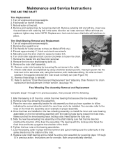
... on Model AR19 only). 4. Manually cycle the drive chain for better access to master link. 6. Free-Wheeling Tine Assembly Removal and Replacement Complete steps 1 through 12 in the same direction as an example of the rotor. 8. Slide the new free-wheeling tine assembly on the AR19 Model. 3. Maintenance and Service Instructions TINE AND TINE SHAFT Tine Replacement 1. Turn off engine and remove weights. 2. Remove and replace tines by reversing steps 1 through 12 in the collar. Remove drive guard cover. 3. Fold handle for...
... on Model AR19 only). 4. Manually cycle the drive chain for better access to master link. 6. Free-Wheeling Tine Assembly Removal and Replacement Complete steps 1 through 12 in the same direction as an example of the rotor. 8. Slide the new free-wheeling tine assembly on the AR19 Model. 3. Maintenance and Service Instructions TINE AND TINE SHAFT Tine Replacement 1. Turn off engine and remove weights. 2. Remove and replace tines by reversing steps 1 through 12 in the collar. Remove drive guard cover. 3. Fold handle for...


