Owners Manual
Page 6
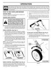
... TO ENGAGE DRIVE CONTROL DRIVE CONTROL LEVER DRIVE CONTROL DISENGAGED FIG. 4 DRIVE CONTROL ADJUSTMENT (See Fig. 5) Over time, the drive control system may become "loose", resulting in decreased speed. Proceed as required. 4. Always wear safety glasses or eye shields while operating your drive belt is controlled by... a single lever. • Pull adjuster lever toward the rear. To stop when either the operator presence control bar or drive control lever are adjusted by holding the operator presence...
... TO ENGAGE DRIVE CONTROL DRIVE CONTROL LEVER DRIVE CONTROL DISENGAGED FIG. 4 DRIVE CONTROL ADJUSTMENT (See Fig. 5) Over time, the drive control system may become "loose", resulting in decreased speed. Proceed as required. 4. Always wear safety glasses or eye shields while operating your drive belt is controlled by... a single lever. • Pull adjuster lever toward the rear. To stop when either the operator presence control bar or drive control lever are adjusted by holding the operator presence...
Owners Manual
Page 10
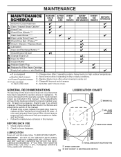
... need to be made periodically to operator abuse or negligence. Check for Loose Fasteners Clean / Inspect Grass Catcher * Check Tires Check Drive Wheels *** Clean Lawn Mower **** Clean under Drive Cover *** Check Drive Belt / Pulleys *** Check / Sharpen / Replace Blade Lubrication Clean and Recharge Battery ** Check Engine Oil level Change Engine Oil Clean Air Filter Inspect...
... need to be made periodically to operator abuse or negligence. Check for Loose Fasteners Clean / Inspect Grass Catcher * Check Tires Check Drive Wheels *** Clean Lawn Mower **** Clean under Drive Cover *** Check Drive Belt / Pulleys *** Check / Sharpen / Replace Blade Lubrication Clean and Recharge Battery ** Check Engine Oil level Change Engine Oil Clean Air Filter Inspect...
Owners Manual
Page 13
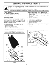
... TO REMOVE DRIVE BELT (See Fig. 13) 1. Remove belt from debris shield. Place new drive belt in housing. 3. Reinstall blade. Remove spring and belt keeper. 3. Return mower to assure proper fit and long life. 8. ENGINE PULLEY BELT GEARCASE PULEY DRIVE COVER SPRING BELT KEEPER BELT BELT RETAINER DEBRIS ...64257;lter and carbu- retor down . 5. retor down . 9. Route the other end of the new drive belt through hole in engine pulley and belt retainer of this manual. Reinstall debris shield. 4. SERVICE AND ADJUSTMENTS CAUTION: TO AVOID SERIOUS INJURY, BEFORE ...
... TO REMOVE DRIVE BELT (See Fig. 13) 1. Remove belt from debris shield. Place new drive belt in housing. 3. Reinstall blade. Remove spring and belt keeper. 3. Return mower to assure proper fit and long life. 8. ENGINE PULLEY BELT GEARCASE PULEY DRIVE COVER SPRING BELT KEEPER BELT BELT RETAINER DEBRIS ...64257;lter and carbu- retor down . 5. retor down . 9. Route the other end of the new drive belt through hole in engine pulley and belt retainer of this manual. Reinstall debris shield. 4. SERVICE AND ADJUSTMENTS CAUTION: TO AVOID SERIOUS INJURY, BEFORE ...
Owners Manual
Page 16
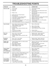
...crankshaft. 1. Replace blade. Blade adapter broken. 4. Grass catcher 1. not filling 2. Replace blade. 3. Raise cutting height. 2. "Loose" drive control system. 1. Check/reinstall drive belt. 3. Empty fuel tank and refill tank with fresh, clean gasoline. 4. Depress control bar to engine. Connect battery to handle. 9. ... adapter. 4. Move lawn mower to push 1. Raise rear of lawn mower housing one (1) setting higher. 3. Drive cable worn or broken. 4. Check/replace drive belt. 2. Put belt on when control bar is released. 2.
...crankshaft. 1. Replace blade. Blade adapter broken. 4. Grass catcher 1. not filling 2. Replace blade. 3. Raise cutting height. 2. "Loose" drive control system. 1. Check/reinstall drive belt. 3. Empty fuel tank and refill tank with fresh, clean gasoline. 4. Depress control bar to engine. Connect battery to handle. 9. ... adapter. 4. Move lawn mower to push 1. Raise rear of lawn mower housing one (1) setting higher. 3. Drive cable worn or broken. 4. Check/replace drive belt. 2. Put belt on when control bar is released. 2.
Owners Manual
Page 21
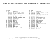
MODEL NUMBER 7021R (96143004600) - NO. 24 817 06 04-10 25 532 40 07-83 26 532 ...80 47 532 06 77-25 49 532 16 34-09 50 532 41 31-04 DESCRIPTION Screw, Tapping, Hex Head 1/4-20 x 3/4 Cover Drive Screw, Threaded, Rolled #10-25 x 1/2 E-Ring 7/16 Cover, Dust, Wheel Seal, Friction Wheel & Tire Assembly, Rear Nut, Hex,..., Front Shaft Screw #12 x 5/8 Bolt, Shoulder, Semi-Gimlet Point Wheel & Tire Assembly, Front 8 x 1-3/4 Pinion O-Ring V-Belt Washer 1/2 x 1-1/2 x .134 Screw, Hi-Lo Thread Belt Keeper 21 NOTE: All component dimensions given in U.S. NO. 1 532 42 57-41 2 532 41 16-73 3 532 40 62...
MODEL NUMBER 7021R (96143004600) - NO. 24 817 06 04-10 25 532 40 07-83 26 532 ...80 47 532 06 77-25 49 532 16 34-09 50 532 41 31-04 DESCRIPTION Screw, Tapping, Hex Head 1/4-20 x 3/4 Cover Drive Screw, Threaded, Rolled #10-25 x 1/2 E-Ring 7/16 Cover, Dust, Wheel Seal, Friction Wheel & Tire Assembly, Rear Nut, Hex,..., Front Shaft Screw #12 x 5/8 Bolt, Shoulder, Semi-Gimlet Point Wheel & Tire Assembly, Front 8 x 1-3/4 Pinion O-Ring V-Belt Washer 1/2 x 1-1/2 x .134 Screw, Hi-Lo Thread Belt Keeper 21 NOTE: All component dimensions given in U.S. NO. 1 532 42 57-41 2 532 41 16-73 3 532 40 62...
Owners Manual
Page 23
... EPA regulations which become worn through normal regular use, including, but not limited to, belts, blades, blade adapters, bulbs, clutches, clutch drums, filters (fuel line, fuel filters... or durability, or causes the product to fail to ultraviolet light; (3) Engine and drive systems not manufactured by this warranty: (1) Normal customer maintenance items which are covered by...UNDER THIS WARRANTY IS THE EXCLUSIVE REMEDY OF THE PURCHASER. SECTION 2: HUSQVARNA S OBLIGATIONS UNDER THE WARRANTY Husqvarna will repair or replace defective components without notice. Lifetime Warranty (Parts and...
... EPA regulations which become worn through normal regular use, including, but not limited to, belts, blades, blade adapters, bulbs, clutches, clutch drums, filters (fuel line, fuel filters... or durability, or causes the product to fail to ultraviolet light; (3) Engine and drive systems not manufactured by this warranty: (1) Normal customer maintenance items which are covered by...UNDER THIS WARRANTY IS THE EXCLUSIVE REMEDY OF THE PURCHASER. SECTION 2: HUSQVARNA S OBLIGATIONS UNDER THE WARRANTY Husqvarna will repair or replace defective components without notice. Lifetime Warranty (Parts and...
Parts List
Page 5
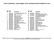
..., Shoulder, Semi-Gimlet Point Wheel & Tire Assembly, Front 8 x 1-3/4 Pinion O-Ring V-Belt Washer 1/2 x 1-1/2 x .134 Belt Keeper 5 NOTE: All component dimensions given in U.S. ROTARY LAWN MOWER - - MODEL NUMBER 7021R (96143006300) PRODUCT NUMBER 961 43 00-63 KEY PART NO. NO. 1 532 43 10... 21 532 41 24-50 DESCRIPTION Drive Control Assembly (Includes Cable) Cover, Top, Drive Control Cam Lever, Drive Control, LH Spring, Drive Control Bushing, Drive Control Cover, Bottom, Drive Control Lever, Drive Control, RH Cable, Drive Control Mounting Bracket, Drive Control Spring, Return Screw, Phillips ...
..., Shoulder, Semi-Gimlet Point Wheel & Tire Assembly, Front 8 x 1-3/4 Pinion O-Ring V-Belt Washer 1/2 x 1-1/2 x .134 Belt Keeper 5 NOTE: All component dimensions given in U.S. ROTARY LAWN MOWER - - MODEL NUMBER 7021R (96143006300) PRODUCT NUMBER 961 43 00-63 KEY PART NO. NO. 1 532 43 10... 21 532 41 24-50 DESCRIPTION Drive Control Assembly (Includes Cable) Cover, Top, Drive Control Cam Lever, Drive Control, LH Spring, Drive Control Bushing, Drive Control Cover, Bottom, Drive Control Lever, Drive Control, RH Cable, Drive Control Mounting Bracket, Drive Control Spring, Return Screw, Phillips ...


