
Owners Manual
Page 3
... of the machine be dangerous if used incorrectly or carelessly, and can result in serious personal injury or the death of nonauthorized accessories or replacement parts. or trimmer can be modified without the permission of California to cause cancer, birth defects or other guards and cutting attachments ....... 18 Adjusting...
... of the machine be dangerous if used incorrectly or carelessly, and can result in serious personal injury or the death of nonauthorized accessories or replacement parts. or trimmer can be modified without the permission of California to cause cancer, birth defects or other guards and cutting attachments ....... 18 Adjusting...

Owners Manual
Page 21
...with a catalytic converter (see chapter on it is leaking fuel. highly inflammable and can result in mind the risk of any part of gasoline and two-stroke engine oil. If your machine is being transported or in storage. • Secure the machine during transport. ...two-stroke engine and must always been run the engine on unleaded gasoline. • The lowest recommended octane grade is recommended. Always use HUSQVARNA two-stroke engine oil, which can cause serious injury when inhaled or allowed to the cutting attachment when the machine is equipped with sparks...
...with a catalytic converter (see chapter on it is leaking fuel. highly inflammable and can result in mind the risk of any part of gasoline and two-stroke engine oil. If your machine is being transported or in storage. • Secure the machine during transport. ...two-stroke engine and must always been run the engine on unleaded gasoline. • The lowest recommended octane grade is recommended. Always use HUSQVARNA two-stroke engine oil, which can cause serious injury when inhaled or allowed to the cutting attachment when the machine is equipped with sparks...

Owners Manual
Page 31
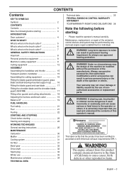
... with a brush once a week, more regularly if conditions are hot and can be regularly cleaned to remove dust and dirt in damage to engine parts • Excessive fuel consumption. Air filter The air filter must be a sign that the performance of the catalytic converter is too ...low (below 4000 rpm), turn the adjuster screw A clockwise until the cutting attachment stops. Cleaning the air filter (555FX, 555FXT) Remove the air filter cover and take out the filter. If your machine is fitted with a cooling system. If...
... with a brush once a week, more regularly if conditions are hot and can be regularly cleaned to remove dust and dirt in damage to engine parts • Excessive fuel consumption. Air filter The air filter must be a sign that the performance of the catalytic converter is too ...low (below 4000 rpm), turn the adjuster screw A clockwise until the cutting attachment stops. Cleaning the air filter (555FX, 555FXT) Remove the air filter cover and take out the filter. If your machine is fitted with a cooling system. If...
Owners Manual
Page 33
... wear guard from the muffler to its normal set-up. Pay particular attention that the opening on the starter to the carburettor by HUSQVARNA. IMPORTANT! x3 • a special air filter cover without air intake (A) • a cover for the filter holder (B) • a ...Any maintenance other brands of the engine. • Preheat the intake air to increase the working temperature of replacement parts can cause severe engine damage. Use only HUSQVARNA replacement parts. Use of other than that routes the hot air from the winter kit as shown in the figure....
... wear guard from the muffler to its normal set-up. Pay particular attention that the opening on the starter to the carburettor by HUSQVARNA. IMPORTANT! x3 • a special air filter cover without air intake (A) • a cover for the filter holder (B) • a ...Any maintenance other brands of the engine. • Preheat the intake air to increase the working temperature of replacement parts can cause severe engine damage. Use only HUSQVARNA replacement parts. Use of other than that routes the hot air from the winter kit as shown in the figure....

Owners Manual
Page 38
... operator's manual. If any warranty maintenance or repairs on your small nonroad engine to a Husqvarna Forest & Garden authorized servicing dealer as soon as listed above) is defective, the part will be repaired or replaced by abuse, neglect or improper maintenance are responsible for the period... be performed at no cost to you are not covered. MAINTENANCE, REPLACEMENT AND REPAIR OF EMISSION-RELATED PARTS Any Husqvarna Forest & Garden approved replacement part used in a reasonable amount of "repair or replace as the carburetor and the ignition system. FEDERAL EMISSION CONTROL ...
... operator's manual. If any warranty maintenance or repairs on your small nonroad engine to a Husqvarna Forest & Garden authorized servicing dealer as soon as listed above) is defective, the part will be repaired or replaced by abuse, neglect or improper maintenance are responsible for the period... be performed at no cost to you are not covered. MAINTENANCE, REPLACEMENT AND REPAIR OF EMISSION-RELATED PARTS Any Husqvarna Forest & Garden approved replacement part used in a reasonable amount of "repair or replace as the carburetor and the ignition system. FEDERAL EMISSION CONTROL ...

Workshop Manual
Page 7
... and carry out Cleaning and Inspection in the order set out in the sections. 3. Look up the page for use Husqvarna's original: • Spare parts • Service tools • Accessories 2.6 Structure This Workshop Manual can be read and understood by personnel who are assumed... Manual describes in detail how to components inside the figures are designated A, B, etc. As these modifications affect service and/or spare parts, specific service information will become out of safety can be dismantled and assembled: 1. Carry out the following steps: Dismantling Cleaning and ...
... and carry out Cleaning and Inspection in the order set out in the sections. 3. Look up the page for use Husqvarna's original: • Spare parts • Service tools • Accessories 2.6 Structure This Workshop Manual can be read and understood by personnel who are assumed... Manual describes in detail how to components inside the figures are designated A, B, etc. As these modifications affect service and/or spare parts, specific service information will become out of safety can be dismantled and assembled: 1. Carry out the following steps: Dismantling Cleaning and ...

Workshop Manual
Page 17
... that the spring and rocker do not fly out. Exercise care to maintain pressure on top of the chain brake band. Always use original spare parts. • Measure the thickness of the brake spring and press in a small screwdriver into the spring. It must be less than 0.6 mm in a ...cylinder cover. Release the brake by using the saw's hand guard as a tool. Fig 3 fully bend upwards until the brake is released and it . Parts Fig 4 must not be replaced if cracked or show signs of other defects. Wear protective goggles. 4 Hold one hand on the spring, and then ...
... that the spring and rocker do not fly out. Exercise care to maintain pressure on top of the chain brake band. Always use original spare parts. • Measure the thickness of the brake spring and press in a small screwdriver into the spring. It must be less than 0.6 mm in a ...cylinder cover. Release the brake by using the saw's hand guard as a tool. Fig 3 fully bend upwards until the brake is released and it . Parts Fig 4 must not be replaced if cracked or show signs of other defects. Wear protective goggles. 4 Hold one hand on the spring, and then ...

Workshop Manual
Page 19
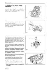
...-14 Nm. • Cylinder cover 3 Warm up the saw will overheat if the mesh is inserted in line with a wire brush. Risk of other defects. Parts must trigger. 6.3 Dismantling the muffler WARNING! When fitting the mesh, make sure that the mesh is clogged resulting in place first. If necessary, use a saw..., the chain brake must be inspected in the right position. See figure 12. The mesh must be replaced, if damaged. If necessary, use original spare parts.
...-14 Nm. • Cylinder cover 3 Warm up the saw will overheat if the mesh is inserted in line with a wire brush. Risk of other defects. Parts must trigger. 6.3 Dismantling the muffler WARNING! When fitting the mesh, make sure that the mesh is clogged resulting in place first. If necessary, use a saw..., the chain brake must be inspected in the right position. See figure 12. The mesh must be replaced, if damaged. If necessary, use original spare parts.

Workshop Manual
Page 20
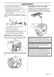
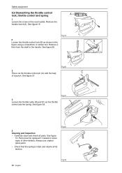
... replace it with a new one . Fig 13 6.6 Dismantling the start/stop control A. Dismantle the air filter holder. Fig 14 20 - Parts must always be replaced if cracked or show signs of other defects. English Safety equipment 6.5 Replacing the chain catcher A worn chain catcher must be...the carburettor" chapter. 2 Loosen screw B and dismantle the stop control 1 Remove the cylinder cover and air filter. Always use original spare parts. Make sure that the vibration element is fitted correctly on the crankcase when a new chain catcher is screwed in place. Cleaning and inspection ...
... replace it with a new one . Fig 13 6.6 Dismantling the start/stop control A. Dismantle the air filter holder. Fig 14 20 - Parts must always be replaced if cracked or show signs of other defects. English Safety equipment 6.5 Replacing the chain catcher A worn chain catcher must be...the carburettor" chapter. 2 Loosen screw B and dismantle the stop control 1 Remove the cylinder cover and air filter. Always use original spare parts. Make sure that the vibration element is fitted correctly on the crankcase when a new chain catcher is screwed in place. Cleaning and inspection ...
Workshop Manual
Page 22
See figure 13. See figure 22. Parts must be replaced if cracked or show signs of a punch. See figure 20. Fig 22 22 - Remove it then from the shaft in the figure ... 4 Loosen the throttle cable (D) and lift out the throttle control and the spring. English Fig 23 Always use original spare parts. • Check that the spring is intact and retains all parts. See figure 21. Fig 19 3 Press out the throttle control pin (C) with the help of other defects. Safety equipment 6.9 Dismantling...
See figure 13. See figure 22. Parts must be replaced if cracked or show signs of a punch. See figure 20. Fig 22 22 - Remove it then from the shaft in the figure ... 4 Loosen the throttle cable (D) and lift out the throttle control and the spring. English Fig 23 Always use original spare parts. • Check that the spring is intact and retains all parts. See figure 21. Fig 19 3 Press out the throttle control pin (C) with the help of other defects. Safety equipment 6.9 Dismantling...

Workshop Manual
Page 25
... four screws, which hold the starter against the crankcase and remove the starter. Fig 3a English - 25 See figures 1 and 2. Cleaning and inspection Clean the parts and check: • The starter cord. • That the starter pawls on the outside of the pulley and remove the pulley. that they spring back...
... four screws, which hold the starter against the crankcase and remove the starter. Fig 3a English - 25 See figures 1 and 2. Cleaning and inspection Clean the parts and check: • The starter cord. • That the starter pawls on the outside of the pulley and remove the pulley. that they spring back...

Workshop Manual
Page 26
Worn or damaged parts must be released. 1 Pull the cord out about 30 cm and lift it into the notch in the starter pulley and turn when the starter ...
Worn or damaged parts must be released. 1 Pull the cord out about 30 cm and lift it into the notch in the starter pulley and turn when the starter ...
Workshop Manual
Page 28
... wrench. tor. Fig 9 Dismantle the tank unit as outlined in the crankcase. See figure 11. Loosen the earth cable. Cleaning and inspection • Clean all parts, especially the tapers on the mandrel with the flywheel. See figure 7. Fig 8 4 Thread the mandrel on the ignition module. Dismantle the intake system, see the...
... wrench. tor. Fig 9 Dismantle the tank unit as outlined in the crankcase. See figure 11. Loosen the earth cable. Cleaning and inspection • Clean all parts, especially the tapers on the mandrel with the flywheel. See figure 7. Fig 8 4 Thread the mandrel on the ignition module. Dismantle the intake system, see the...

Workshop Manual
Page 30
... Remove the clutch shoe springs from the side that does not have text. Cleaning and inspection • Clean and check all parts carefully. Always use original spare parts. • Check the thickness of other defects. Fig 16 Min 60 mm 30 - Be careful with slide callipers across the... whole clutch hub. Parts must be replaced if cracked or showing signs of the clutch shoes by moving the kickback guard backwards. Repair Instructions 7.8 Dismantling the ...
... Remove the clutch shoe springs from the side that does not have text. Cleaning and inspection • Clean and check all parts carefully. Always use original spare parts. • Check the thickness of other defects. Fig 16 Min 60 mm 30 - Be careful with slide callipers across the... whole clutch hub. Parts must be replaced if cracked or showing signs of the clutch shoes by moving the kickback guard backwards. Repair Instructions 7.8 Dismantling the ...

Workshop Manual
Page 31
... tank. Dismantle the centrifugal clutch as outlined in the clutch (anti-clockwise) until it together with chain oil. Always use original spare parts. • Lubricate all parts carefully. 7.9 Assembly of centrifugal clutch 1 Insert the clutch springs on the oil pump from the crankcase and remove it stops. Then ... See figure 19. 4 Loosen the screws on the side of other defects. Fig 18 Fig 19 Fig 20 Repair Instructions English - 31 Parts must be replaced if cracked or showing signs of the shoes without text. Cleaning and inspection • Clean and check all moving...
... tank. Dismantle the centrifugal clutch as outlined in the clutch (anti-clockwise) until it together with chain oil. Always use original spare parts. • Lubricate all parts carefully. 7.9 Assembly of centrifugal clutch 1 Insert the clutch springs on the oil pump from the crankcase and remove it stops. Then ... See figure 19. 4 Loosen the screws on the side of other defects. Fig 18 Fig 19 Fig 20 Repair Instructions English - 31 Parts must be replaced if cracked or showing signs of the shoes without text. Cleaning and inspection • Clean and check all moving...

Workshop Manual
Page 33
...figure 24. Knock out the POP-out window using the POP-out hole and the fuel hose hole. Cleaning and inspection Clean and check all parts carefully. Fit the rubber grommet to their attachments. Loosen the lower screws of other defects. Fit the other screws. See figure 24. Press ...! Pull up and then outward. Push the tank back in place on its bracket on the intake system (J). See figure 26. Always use original spare parts. 7.13 Assembling the intake system 1 Assemble the intake system. 2 Fit the lower screws of the intake system using a screwdriver. Fig 25b Fig 26 ...
...figure 24. Knock out the POP-out window using the POP-out hole and the fuel hose hole. Cleaning and inspection Clean and check all parts carefully. Fit the rubber grommet to their attachments. Loosen the lower screws of other defects. Fit the other screws. See figure 24. Press ...! Pull up and then outward. Push the tank back in place on its bracket on the intake system (J). See figure 26. Always use original spare parts. 7.13 Assembling the intake system 1 Assemble the intake system. 2 Fit the lower screws of the intake system using a screwdriver. Fig 25b Fig 26 ...

Workshop Manual
Page 35
...and fuel is closed and the choke valve H is supplied through all the diffuser jets D, E, and F. The throttle valve, J, is partly open. The throttle valve I is partly open and the choke valve H is completely shut. The throttle valve, J, starts to suck from all four diffuser jets (D, E, F ...the full throttle mode both valves are closed . The throttle valve, J, is supplied through the diffuser jets D and E. Fig 30 In part throttle mode, the throttle valve I is fully open. See figure 32. Function The carburettor operates differently in the following modes: • ...
...and fuel is closed and the choke valve H is supplied through all the diffuser jets D, E, and F. The throttle valve, J, is partly open. The throttle valve I is partly open and the choke valve H is completely shut. The throttle valve, J, starts to suck from all four diffuser jets (D, E, F ...the full throttle mode both valves are closed . The throttle valve, J, is supplied through the diffuser jets D and E. Fig 30 In part throttle mode, the throttle valve I is fully open. See figure 32. Function The carburettor operates differently in the following modes: • ...
Workshop Manual
Page 43
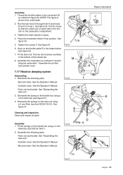
... the intake bellow. See figure 53. 5. See figure 51. 6. See figure 50. 7. Assemble the air filter and cylinder cover. Dismantle the following parts: •Tank unit and handle. Assembly 1. Fit the tank unit. See the Operator's Manual. •Tank unit and handle. See figure 57. ... on each side of the handle bar. 8. Assembly 1. NOTE! Tighten the screws F. Fig 54 7.17 Vibration damping system Dismantling 1. Assemble the following parts: •Bar and chain. See figure 55. The two short screws are on the tank unit using a 4 mm Allen key (see figure 57)....
... the intake bellow. See figure 53. 5. See figure 51. 6. See figure 50. 7. Assemble the air filter and cylinder cover. Dismantle the following parts: •Tank unit and handle. Assembly 1. Fit the tank unit. See the Operator's Manual. •Tank unit and handle. See figure 57. ... on each side of the handle bar. 8. Assembly 1. NOTE! Tighten the screws F. Fig 54 7.17 Vibration damping system Dismantling 1. Assemble the following parts: •Bar and chain. See figure 55. The two short screws are on the tank unit using a 4 mm Allen key (see figure 57)....

Workshop Manual
Page 46
... Fig 68 46 - Repair Instructions Check the following: • That the cylinder's surface coating is intact. • Pressure test the decompression valve. Especially the upper part of the cylinder. • That the cylinder does not have any chafe or cutting marks. • That the piston is not burnt into its groove...
... Fig 68 46 - Repair Instructions Check the following: • That the cylinder's surface coating is intact. • Pressure test the decompression valve. Especially the upper part of the cylinder. • That the cylinder does not have any chafe or cutting marks. • That the piston is not burnt into its groove...

Workshop Manual
Page 50
... them off all gasket remains from the contact surfaces on the sides. 3. Repair Instructions 7. English Fig 74 Fig 75 B. Fig 72 8. Fig 73 Clean all parts and scrape off using the 531 00 48-67 pulling device. That the big-end bearing does not have any dirt and foreign particles from...
... them off all gasket remains from the contact surfaces on the sides. 3. Repair Instructions 7. English Fig 74 Fig 75 B. Fig 72 8. Fig 73 Clean all parts and scrape off using the 531 00 48-67 pulling device. That the big-end bearing does not have any dirt and foreign particles from...


