
Operation Manual
Page 2
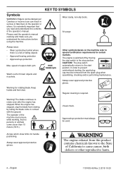
...ricochets. 10000 Warning for handle positioning. Regular cleaning is a risk of the operator's manual. Arrows which show limits for rotating blade. Always wear approved protective gloves. Please read and understand the contents of falling objects • Approved hearing protection • Approved...helmet where there is required. Other symbols/decals on the machine refer to rotate even after the engine has stopped. The blade continues to special certification requirements for certain markets. Symbols WARNING! Careless or incorrect use can be dangerous! CAUTION!...
...ricochets. 10000 Warning for handle positioning. Regular cleaning is a risk of the operator's manual. Arrows which show limits for rotating blade. Always wear approved protective gloves. Please read and understand the contents of falling objects • Approved hearing protection • Approved...helmet where there is required. Other symbols/decals on the machine refer to rotate even after the engine has stopped. The blade continues to special certification requirements for certain markets. Symbols WARNING! Careless or incorrect use can be dangerous! CAUTION!...
Operation Manual
Page 3
... 6 Personal protective equipment 6 Machine′s safety equipment 7 ASSEMBLY Fitting the loop handle 11 Assembling the angle gear 11 Assembling the cutting equipment 11 Assembling the blade 11 FUEL HANDLING Fuel safety 12 Fuel 12 Fueling 13 STARTING AND STOPPING Check before starting 14 Starting and stopping 14 WORKING TECHNIQUES General working...
... 6 Personal protective equipment 6 Machine′s safety equipment 7 ASSEMBLY Fitting the loop handle 11 Assembling the angle gear 11 Assembling the cutting equipment 11 Assembling the blade 11 FUEL HANDLING Fuel safety 12 Fuel 12 Fueling 13 STARTING AND STOPPING Check before starting 14 Starting and stopping 14 WORKING TECHNIQUES General working...
Operation Manual
Page 5
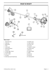
WHAT IS WHAT? 1 3 2 4 21 19 22 20 18 23 24 5 6 17 7 8 12 13 14 9 10 11 15 16 What is what? 1 Grease filler cap 2 Angle gear 3 Blade guard 4 Shaft 5 Loop handle 6 Handle adjustment 7 Stop switch 8 Throttle trigger lockout 9 Throttle trigger 10 Choke control 11 Air purge 12 Spark plug cap and spark plug 13 Cylinder cover 14 Starter handle 15 Air filter cover 16 Fuel tank 17 Operator's manual 18 Locking screw 19 Washers 20 Support flange 21 Blade 22 Drive disc 23 Allen key 24 Socket spanner 1157433-49 Rev. 2 2015-10-20 English - 5
WHAT IS WHAT? 1 3 2 4 21 19 22 20 18 23 24 5 6 17 7 8 12 13 14 9 10 11 15 16 What is what? 1 Grease filler cap 2 Angle gear 3 Blade guard 4 Shaft 5 Loop handle 6 Handle adjustment 7 Stop switch 8 Throttle trigger lockout 9 Throttle trigger 10 Choke control 11 Air purge 12 Spark plug cap and spark plug 13 Cylinder cover 14 Starter handle 15 Air filter cover 16 Fuel tank 17 Operator's manual 18 Locking screw 19 Washers 20 Support flange 21 Blade 22 Drive disc 23 Allen key 24 Socket spanner 1157433-49 Rev. 2 2015-10-20 English - 5
Operation Manual
Page 10
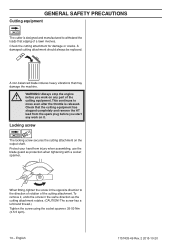
... heavy vibrations that the cutting equipment has stopped completely and remove the HT lead from injury when assembling, use the blade guard as the cutting attachment rotates. (CAUTION! Always stop the engine ! To remove it . WARNING! This continues to move even after the throttle is designed ...
... heavy vibrations that the cutting equipment has stopped completely and remove the HT lead from injury when assembling, use the blade guard as the cutting attachment rotates. (CAUTION! Always stop the engine ! To remove it . WARNING! This continues to move even after the throttle is designed ...
Operation Manual
Page 11
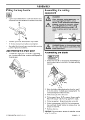
... it can result in serious and/or fatal personal injury. • Slide the spacer into the slot in the drive disc. 3 Fit the blade (B) on the drive disc/support flange ! WARNING! English - 11 Note that the raised section on the drive disc. 4 Fit the.... 7 Remove allen key. CAUTION! Tighten the bolt/knob. Tighten the locking screw to a torque of the cutting attachment. CAUTION! Assembling the blade 1 Fit the drive disc (A) on the suppporting tube. Do not forget to give a comfortable working position. Fitting the loop handle ASSEMBLY Assembling...
... it can result in serious and/or fatal personal injury. • Slide the spacer into the slot in the drive disc. 3 Fit the blade (B) on the drive disc/support flange ! WARNING! English - 11 Note that the raised section on the drive disc. 4 Fit the.... 7 Remove allen key. CAUTION! Tighten the bolt/knob. Tighten the locking screw to a torque of the cutting attachment. CAUTION! Assembling the blade 1 Fit the drive disc (A) on the suppporting tube. Do not forget to give a comfortable working position. Fitting the loop handle ASSEMBLY Assembling...
Operation Manual
Page 14
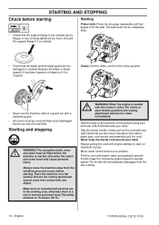
Replace the blade or blade guard if it has been exposed to impact or if it is cracked. Choke: Set the choke control in the choke position. • Never use ... with any object. Ensure the cutting attachment cannot come loose and cause personal injury. STARTING AND STOPPING Check before starting • Check that the blade and the blade guard are in either the choke or start throttle positions the cutting attachment will automatically disengage from the refueling area and source before starting...
Replace the blade or blade guard if it has been exposed to impact or if it is cracked. Choke: Set the choke control in the choke position. • Never use ... with any object. Ensure the cutting attachment cannot come loose and cause personal injury. STARTING AND STOPPING Check before starting • Check that the blade and the blade guard are in either the choke or start throttle positions the cutting attachment will automatically disengage from the refueling area and source before starting...
Operation Manual
Page 16
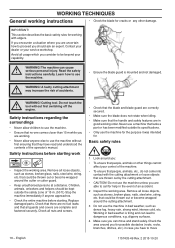
...read and understood the contents of 15 m. (50 ft.) Stop the machine immediately if anyone else to use the machine. • Ensure the blade guard is tiring and can cause ! tool without first ensuring that the handle and safety features are complete and fastened securely. Check all guards...Rev. 2 2015-10-20 Check that there are no -one comes closer than 15 m while you are correctly secured. • Make sure the blade does not rotate when idling. • Make sure that they have to use the machine without first switching off the engine. Basic safety ...
...read and understood the contents of 15 m. (50 ft.) Stop the machine immediately if anyone else to use the machine. • Ensure the blade guard is tiring and can cause ! tool without first ensuring that the handle and safety features are complete and fastened securely. Check all guards...Rev. 2 2015-10-20 Check that there are no -one comes closer than 15 m while you are correctly secured. • Make sure the blade does not rotate when idling. • Make sure that they have to use the machine without first switching off the engine. Basic safety ...

Operation Manual
Page 17
... your hands and feet away from the spark plug. Repair any load on sloping ground. • When the engine is switched off, keep the blade close to the ground. • Always slow the engine to remove the cut material while the engine is running . Neither the operator of your ...ensure you are using the machine) can get burnt if you have a safe and stable working on the engine (i.e. Never swing the machine around the blade shaft as this can be kept outside the safety zone of injury. Long periods at a distance. Children, animals, onlookers and helpers should be thrown...
... your hands and feet away from the spark plug. Repair any load on sloping ground. • When the engine is switched off, keep the blade close to the ground. • Always slow the engine to remove the cut material while the engine is running . Neither the operator of your ...ensure you are using the machine) can get burnt if you have a safe and stable working on the engine (i.e. Never swing the machine around the blade shaft as this can be kept outside the safety zone of injury. Long periods at a distance. Children, animals, onlookers and helpers should be thrown...

Operation Manual
Page 22
... the Maintenance section. Fill if necessary using special grease. X Make sure the throttle trigger lock and the throttle function correctly from carbon deposits. X Check the blade for cracks and chips or damage. X Check that the spark plug is fitted with a suppressor. Replace if necessary by an autorized service workshop. Clean...
... the Maintenance section. Fill if necessary using special grease. X Make sure the throttle trigger lock and the throttle function correctly from carbon deposits. X Check the blade for cracks and chips or damage. X Check that the spark plug is fitted with a suppressor. Replace if necessary by an autorized service workshop. Clean...
Operation Manual
Page 23
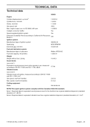
speed, rear/front handles: 9,1/4,2 Cutting equipment Blade 503 84 82-02 NOTE! This spark ignition system complies with the Canadian ICES-002 standard. Note 2: Reported data for the machine has a typical statistical ... data for equivalent sound pressure level for equivalent vibration level has a typical statistical dispersion (standard deviation) of 1 dB (A). engine output, acc. TECHNICAL DATA Technical data 525ES Engine Cylinder displacement, cu.in/cm3 1,55/25,4 Cylinder bore, inch/mm 1,34/34 Stroke, inch/mm 1,10/28 Idle speed, rpm 3000 Max. to...
speed, rear/front handles: 9,1/4,2 Cutting equipment Blade 503 84 82-02 NOTE! This spark ignition system complies with the Canadian ICES-002 standard. Note 2: Reported data for the machine has a typical statistical ... data for equivalent sound pressure level for equivalent vibration level has a typical statistical dispersion (standard deviation) of 1 dB (A). engine output, acc. TECHNICAL DATA Technical data 525ES Engine Cylinder displacement, cu.in/cm3 1,55/25,4 Cylinder bore, inch/mm 1,34/34 Stroke, inch/mm 1,10/28 Idle speed, rpm 3000 Max. to...


