Owner's Manual
Page 5
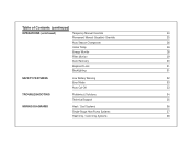
Table of Contents (continued) OPERATIONS (continued) Temporary Manual Override 24 Permanent Manual (Vacation) Override 25 Auto Season Changeover 26 Home Today 26 Energy Monitor 28 Filter Monitor 29 Auto Recovery 30 Keyboard Lock 31 Backlighting 31 SAFETY FEATURES Low Battery Warning 32 Error Mode 33 Auto Cut-Off 33 TROUBLESHOOTING Problems & Solutions 34 Technical Support 35 WIRING DIAGRAMS Heat / Cool Systems 36 Single-Stage Heat Pump Systems 37 Heat Only / Cool Only Systems 38
Table of Contents (continued) OPERATIONS (continued) Temporary Manual Override 24 Permanent Manual (Vacation) Override 25 Auto Season Changeover 26 Home Today 26 Energy Monitor 28 Filter Monitor 29 Auto Recovery 30 Keyboard Lock 31 Backlighting 31 SAFETY FEATURES Low Battery Warning 32 Error Mode 33 Auto Cut-Off 33 TROUBLESHOOTING Problems & Solutions 34 Technical Support 35 WIRING DIAGRAMS Heat / Cool Systems 36 Single-Stage Heat Pump Systems 37 Heat Only / Cool Only Systems 38
Owner's Manual
Page 6
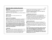
This Hunter Thermostat will NOT control multi-stage heat pumps or 110/220 Volt systems. INSTALLATION 2 All installation is lower than 32°F (0°C). Any change to the set temperature will display room temperatures from ... you begin to install or operate your Hunter Thermostat. Note: At initial power-up this thermostat is below 32°F (0°C). It does not provide a delay when there are power outages. "LO" will also operate single-stage heat pumps that this delay also applies to the heating system control. See page 25 for Cool...
This Hunter Thermostat will NOT control multi-stage heat pumps or 110/220 Volt systems. INSTALLATION 2 All installation is lower than 32°F (0°C). Any change to the set temperature will display room temperatures from ... you begin to install or operate your Hunter Thermostat. Note: At initial power-up this thermostat is below 32°F (0°C). It does not provide a delay when there are power outages. "LO" will also operate single-stage heat pumps that this delay also applies to the heating system control. See page 25 for Cool...
Owner's Manual
Page 11
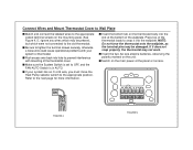
... provides electricity to non-battery powered thermostats. s Remove existing wallplate. s The number of the thermostat from O, B, or R Reversing Valve (Single-stage Heat Pumps only) O/B O/B O/B the wall. This air could cause a false thermostat reading. Tape up the wire and do not have to be as few ... labeling procedures correctly, you may want to tape them from the existing thermostat terminals. s If hole in wall is larger than necessary for heat pumps W Y/Y1 Y/Y1 W W wires do GY Air Conditioning Compressor Y/Y1 not always comply with a code letter as eight, or any ...
... provides electricity to non-battery powered thermostats. s Remove existing wallplate. s The number of the thermostat from O, B, or R Reversing Valve (Single-stage Heat Pumps only) O/B O/B O/B the wall. This air could cause a false thermostat reading. Tape up the wire and do not have to be as few ... labeling procedures correctly, you may want to tape them from the existing thermostat terminals. s If hole in wall is larger than necessary for heat pumps W Y/Y1 Y/Y1 W W wires do GY Air Conditioning Compressor Y/Y1 not always comply with a code letter as eight, or any ...
Owner's Manual
Page 13
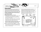
... main power at the bottom of the thermostat cover. s Be sure to prevent interference with your system has an O or B wire, you must move the Heat Pump selector switch to the old thermostat. s Insert the bottom tab on the thermostat body into the slot at the panel or furnace. NOTE: Do not...
... main power at the bottom of the thermostat cover. s Be sure to prevent interference with your system has an O or B wire, you must move the Heat Pump selector switch to the old thermostat. s Insert the bottom tab on the thermostat body into the slot at the panel or furnace. NOTE: Do not...
Owner's Manual
Page 14
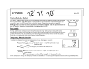
... Reversing Valve type. O - Leave it in COOL mode. If you have a single-stage Heat Pump (no effect in the "HG" position. NOTE: When changing these features after installation, move the HEAT / COOL selector switch to control your system, the system type must be specified by selector switches..." position is in the cooling mode. The system selector has no auxiliary or emergency heat source), then slide the switch to "O" for your needs. HE switch) The factory position for this Hunter thermostat to OFF before removing the thermostat from the wall. switch HG - INSTALLATION 14...
... Reversing Valve type. O - Leave it in COOL mode. If you have a single-stage Heat Pump (no effect in the "HG" position. NOTE: When changing these features after installation, move the HEAT / COOL selector switch to control your system, the system type must be specified by selector switches..." position is in the cooling mode. The system selector has no auxiliary or emergency heat source), then slide the switch to "O" for your needs. HE switch) The factory position for this Hunter thermostat to OFF before removing the thermostat from the wall. switch HG - INSTALLATION 14...
Owner's Manual
Page 24
... The Fan switch should normally be turned on with normal operation of a rapid system On-Off. For electric heat, air conditioning, and heat pump operation, the Fan will be set temperature without affecting your program: Press and hold Press and or for it to prevent the ...possibility of your desired new temperature. 8 6 : 7 8 M T W Th F Sa Su SET TEMP AM °C PM H 73 AUTO COOL HEAT TEMP °HC s Press to ...
... The Fan switch should normally be turned on with normal operation of a rapid system On-Off. For electric heat, air conditioning, and heat pump operation, the Fan will be set temperature without affecting your program: Press and hold Press and or for it to prevent the ...possibility of your desired new temperature. 8 6 : 7 8 M T W Th F Sa Su SET TEMP AM °C PM H 73 AUTO COOL HEAT TEMP °HC s Press to ...
Owner's Manual
Page 34
... ensure there is installed between the RC and RH terminals. 8. Make sure your furnace blower door is not in the correct position ("HEAT," "COOL" or "AUTO"). 2. If your circuit breakers and switches to opposite position 1. TROUBLESHOOTING 34-35 Problem SCRAMBLED OR DOUBLE DISPLAY... be in for the correct day setting. 1. The thermostat may be as much as a 4 minute delay before changing from Heat or Cool. 3. Check the position of the Furnace or Heat Pump selector switch: Normal / O / B. Check for two seconds. 1. Check battery connections and batteries. 2. Look for "AUTO"...
... ensure there is installed between the RC and RH terminals. 8. Make sure your furnace blower door is not in the correct position ("HEAT," "COOL" or "AUTO"). 2. If your circuit breakers and switches to opposite position 1. TROUBLESHOOTING 34-35 Problem SCRAMBLED OR DOUBLE DISPLAY... be in for the correct day setting. 1. The thermostat may be as much as a 4 minute delay before changing from Heat or Cool. 3. Check the position of the Furnace or Heat Pump selector switch: Normal / O / B. Check for two seconds. 1. Check battery connections and batteries. 2. Look for "AUTO"...
Owner's Manual
Page 37
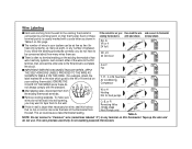
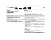
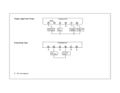
No Connection Single-stage Heat Pump 2-wire Heat Only Jumper RC RH Heat Pump 24V Supply THERMOSTAT G W X Fan Relay Y O/B Compressor Reversing Contactor Valve THERMOSTAT RC RH G W Y O/B X X X X Heat 24V Supply Heat Relay or Valve X -
No Connection Single-stage Heat Pump 2-wire Heat Only Jumper RC RH Heat Pump 24V Supply THERMOSTAT G W X Fan Relay Y O/B Compressor Reversing Contactor Valve THERMOSTAT RC RH G W Y O/B X X X X Heat 24V Supply Heat Relay or Valve X -


