Owner's Manual
Page 3
Table of Contents Important Information 5 Tools 6 Uninstalling the Existing Unit 7 Installing the Thermostat 12 installing the wall plate 12 connecting the wires 16 attaching the thermostat 18 Settings 22 Methods of Operation 26 manual operation 28 default programs 32 creating custom programs 34 Icons and Features 38 Wiring 49 Troubleshooting 52 3
Table of Contents Important Information 5 Tools 6 Uninstalling the Existing Unit 7 Installing the Thermostat 12 installing the wall plate 12 connecting the wires 16 attaching the thermostat 18 Settings 22 Methods of Operation 26 manual operation 28 default programs 32 creating custom programs 34 Icons and Features 38 Wiring 49 Troubleshooting 52 3

Owner's Manual
Page 7
Do not disconnect the wires from the existing thermostat before reading these instructions. The wires must be labeled prior to removal to ensure proper reconnection. 7 NOTICE!
Do not disconnect the wires from the existing thermostat before reading these instructions. The wires must be labeled prior to removal to ensure proper reconnection. 7 NOTICE!
Owner's Manual
Page 9
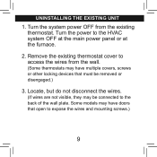
Turn the power to the back of the wall plate. Locate, but do not disconnect the wires. (If wires are not visible, they may be removed or disengaged.) 3. Remove the existing thermostat cover to expose the wires and mounting screws.) 9 Some models may have doors that must be connected to the HVAC system OFF at the main power panel or at the furnace. 2. uninstalling the existing unit 1. Turn the system power OFF from the wall. (Some thermostats may have multiple covers, screws or other locking devices that open to access the wires from the existing thermostat.
Turn the power to the back of the wall plate. Locate, but do not disconnect the wires. (If wires are not visible, they may be removed or disengaged.) 3. Remove the existing thermostat cover to expose the wires and mounting screws.) 9 Some models may have doors that must be connected to the HVAC system OFF at the main power panel or at the furnace. 2. uninstalling the existing unit 1. Turn the system power OFF from the wall. (Some thermostats may have multiple covers, screws or other locking devices that open to access the wires from the existing thermostat.

Owner's Manual
Page 10
Y1 G W/B Y/0 RC RH if your existing thermostat is marked... RH / R / VR / 4 RC / VC Y / C* / M / O label the wire with this sticker: 24 Volt RH 24 Volt cool RC air conditioning compressor W / H / B G / F Y1 heating fan heat pump compressor Y/0 W/B G Y1 10
Y1 G W/B Y/0 RC RH if your existing thermostat is marked... RH / R / VR / 4 RC / VC Y / C* / M / O label the wire with this sticker: 24 Volt RH 24 Volt cool RC air conditioning compressor W / H / B G / F Y1 heating fan heat pump compressor Y/0 W/B G Y1 10

Owner's Manual
Page 11
... Y & C are not labeled, contact a qualified HVAC technician.) W RC Y G W Note: Wire colors do not connect it to the wall as you have a wire marked C, do not always comply with standards, so wire color should not be ignored. Using the provided stickers, label each wire and remove the existing wall plate. 11 Refer to the existing...
... Y & C are not labeled, contact a qualified HVAC technician.) W RC Y G W Note: Wire colors do not connect it to the wall as you have a wire marked C, do not always comply with standards, so wire color should not be ignored. Using the provided stickers, label each wire and remove the existing wall plate. 11 Refer to the existing...
Owner's Manual
Page 13
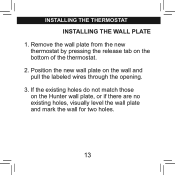
installing the thermostat INSTALLING THE WALL PLATE 1. Position the new wall plate on the Hunter wall plate, or if there are no existing holes, visually level the wall plate and mark the wall for two holes. 13 If the existing holes do not match those on the wall and pull the labeled wires through the opening. 3. Remove the wall plate from the new thermostat by pressing the release tab on the bottom of the thermostat. 2.
installing the thermostat INSTALLING THE WALL PLATE 1. Position the new wall plate on the Hunter wall plate, or if there are no existing holes, visually level the wall plate and mark the wall for two holes. 13 If the existing holes do not match those on the wall and pull the labeled wires through the opening. 3. Remove the wall plate from the new thermostat by pressing the release tab on the bottom of the thermostat. 2.
Owner's Manual
Page 15
Reposition the wall plate on the wall, pulling the wires through the wall plate and into the holes until they are flush with the wall. 6. Remove the wall plate and drill two 3/16" holes where marked. 5. Insert the mounting screws through the opening. installing the thermostat, cont. 4. Verify that the wall plate is visually level and securely tighten both screws. 15 Tap the plastic anchors into the anchors.
Reposition the wall plate on the wall, pulling the wires through the wall plate and into the holes until they are flush with the wall. 6. Remove the wall plate and drill two 3/16" holes where marked. 5. Insert the mounting screws through the opening. installing the thermostat, cont. 4. Verify that the wall plate is visually level and securely tighten both screws. 15 Tap the plastic anchors into the anchors.

Owner's Manual
Page 17
...Y W place. Tighten each screw after the connection has been made. (The ends of any excess wire length back into the wall.) 3. CONNECTING THE WIRES 1. If you do not have both an RH and RC wire. Note: A jumper wire has been provided, connecting the RC and RH terminals for systems that do not remove, the... terminal screws. If you have both an RH and RC wire, leave the jumper in electrical tape and carefully pushed back into the wall to the terminals as shown. Push any extra wires should be wrapped in 2. Loosen, but do not provide both an RH and RC...
...Y W place. Tighten each screw after the connection has been made. (The ends of any excess wire length back into the wall.) 3. CONNECTING THE WIRES 1. If you do not have both an RH and RC wire. Note: A jumper wire has been provided, connecting the RC and RH terminals for systems that do not remove, the... terminal screws. If you have both an RH and RC wire, leave the jumper in electrical tape and carefully pushed back into the wall to the terminals as shown. Push any extra wires should be wrapped in 2. Loosen, but do not provide both an RH and RC...

Owner's Manual
Page 49
Wiring 49
Wiring 49

Owner's Manual
Page 50
Wiring, CONT. 50
Wiring, CONT. 50

Owner's Manual
Page 51
Wiring, CONT. 51
Wiring, CONT. 51

Owner's Manual
Page 53
... power to the desired position. 5 b. My heating or cooling will come on or off to protect the compressor. 5 c. Replace the batteries. 5 e. If your system has 4 wires, ensure the jumper wire is closed properly. 5 f. There may be as much as a 4-minute delay before the system turns on or off . 5 a. troubleshooting 5. Wait.
... power to the desired position. 5 b. My heating or cooling will come on or off to protect the compressor. 5 c. Replace the batteries. 5 e. If your system has 4 wires, ensure the jumper wire is closed properly. 5 f. There may be as much as a 4-minute delay before the system turns on or off . 5 a. troubleshooting 5. Wait.


