
Owner's Manual
Page 3
Set & $ave Programmable ermostat installation and operation manual Model 44110 42707-01 3-7-06
Set & $ave Programmable ermostat installation and operation manual Model 44110 42707-01 3-7-06
Owner's Manual
Page 5
Table of Contents Important Information 5 Tools 6 Uninstalling the Existing Unit 7 Installing the Thermostat 12 installing the wall plate 12 connecting the wires 16 attaching the thermostat 18 Settings 22 Methods of Operation 26 manual operation 28 default programs 32 creating custom programs 34 Icons and Features 38 Troubleshooting 49 3
Table of Contents Important Information 5 Tools 6 Uninstalling the Existing Unit 7 Installing the Thermostat 12 installing the wall plate 12 connecting the wires 16 attaching the thermostat 18 Settings 22 Methods of Operation 26 manual operation 28 default programs 32 creating custom programs 34 Icons and Features 38 Troubleshooting 49 3
Owner's Manual
Page 6
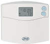
Your new Hunter thermostat will provide years of reliable service and year-round energy savings. Thank you for complete operation instructions. 4 Please read this manual before beginning installation and save this booklet for choosing a Hunter programmable thermostat. Set & Save Programmable Thermostat Model 44110 Congratulations!
Your new Hunter thermostat will provide years of reliable service and year-round energy savings. Thank you for complete operation instructions. 4 Please read this manual before beginning installation and save this booklet for choosing a Hunter programmable thermostat. Set & Save Programmable Thermostat Model 44110 Congratulations!

Owner's Manual
Page 8
To install your new thermostat, you will need the following supplies: Flat-head screwdriver Small Phillips-head screwdriver Hammer Electric drill and 3/16" bit Two 1.5 Volt (AA) size alkaline batteries 6 TOOLS This thermostat includes two #8 slotted screws and two wall anchors for mounting.
To install your new thermostat, you will need the following supplies: Flat-head screwdriver Small Phillips-head screwdriver Hammer Electric drill and 3/16" bit Two 1.5 Volt (AA) size alkaline batteries 6 TOOLS This thermostat includes two #8 slotted screws and two wall anchors for mounting.
Owner's Manual
Page 15
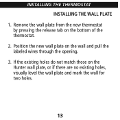
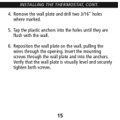
Position the new wall plate on the bottom of the thermostat. 2. Remove the wall plate from the new thermostat by pressing the release tab on the wall and pull the labeled wires through the opening. 3. If the existing holes do not match those on the Hunter wall plate, or if there are no existing holes, visually level the wall plate and mark the wall for two holes. 13 INSTALLING THE THERMOSTAT INSTALLING THE WALL PLATE 1.
Position the new wall plate on the bottom of the thermostat. 2. Remove the wall plate from the new thermostat by pressing the release tab on the wall and pull the labeled wires through the opening. 3. If the existing holes do not match those on the Hunter wall plate, or if there are no existing holes, visually level the wall plate and mark the wall for two holes. 13 INSTALLING THE THERMOSTAT INSTALLING THE WALL PLATE 1.
Owner's Manual
Page 17
INSTALLING THE THERMOSTAT, CONT. 4. Tap the plastic anchors into the anchors. Insert the mounting screws through the opening. Reposition the wall plate on the wall, pulling the wires through the wall plate and into the holes until they are flush with the wall. 6. Verify that the wall plate is visually level and securely tighten both screws. 15 Remove the wall plate and drill two 3/16" holes where marked. 5.
INSTALLING THE THERMOSTAT, CONT. 4. Tap the plastic anchors into the anchors. Insert the mounting screws through the opening. Reposition the wall plate on the wall, pulling the wires through the wall plate and into the holes until they are flush with the wall. 6. Verify that the wall plate is visually level and securely tighten both screws. 15 Remove the wall plate and drill two 3/16" holes where marked. 5.
Owner's Manual
Page 19
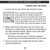
... the terminals as shown. Match and connect the wires from the wall to prevent interference. 17 Wires should be inserted behind the black terminal shields. INSTALLING THE THERMOSTAT, CONT. If you do not remove, the terminal screws.
... the terminals as shown. Match and connect the wires from the wall to prevent interference. 17 Wires should be inserted behind the black terminal shields. INSTALLING THE THERMOSTAT, CONT. If you do not remove, the terminal screws.
Owner's Manual
Page 21
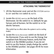
... SYSTEM to OFF and the FAN switch to HE for electric furnaces. (The switch has no effect when the system is in the ENABLE position. INSTALLING THE THERMOSTAT, CONT. Locate the A R switch on the back of the thermostat. See pages 44-45 for gas furnace and oil burners...
... SYSTEM to OFF and the FAN switch to HE for electric furnaces. (The switch has no effect when the system is in the ENABLE position. INSTALLING THE THERMOSTAT, CONT. Locate the A R switch on the back of the thermostat. See pages 44-45 for gas furnace and oil burners...

Owner's Manual
Page 23
Insert two AA alkaline batteries. 6. Note: Do not force the thermostat onto the wall plate, as the terminal pins may not work. 5. Restore power at the electrical panel or furnace. 21 INSTALLING THE THERMOSTAT, CONT. 4. If the thermostat does not snap into place. Place the top of the thermostat over the two tabs on the wall plate. Press the thermostat onto the wall plate and press to snap the bottom tab into place properly, the unit may be damaged.
Insert two AA alkaline batteries. 6. Note: Do not force the thermostat onto the wall plate, as the terminal pins may not work. 5. Restore power at the electrical panel or furnace. 21 INSTALLING THE THERMOSTAT, CONT. 4. If the thermostat does not snap into place. Place the top of the thermostat over the two tabs on the wall plate. Press the thermostat onto the wall plate and press to snap the bottom tab into place properly, the unit may be damaged.
Owner's Manual
Page 43
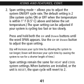
... span cycle will increase your cycle time by causing the system to adjust the system ON/OFF cycle rate. Span setting mode - When batteries are installed, or the unit is cycling too fast or too slowly.
... span cycle will increase your cycle time by causing the system to adjust the system ON/OFF cycle rate. Span setting mode - When batteries are installed, or the unit is cycling too fast or too slowly.
Owner's Manual
Page 45
...battery power is left, the battery icon will flash alone on the display and your system will turn off until new AA alkaline batteries are installed. 43 When the batteries are detected as weak, the icon will remain off . If the batteries become too weak for normal operation, ...the thermostat enters the second battery power shortage mode. The system will flash until new batteries are installed. (Your programs and time settings will be lost if the batteries are not replaced within one minute.) The thermostat will resume normal operation after...
...battery power is left, the battery icon will flash alone on the display and your system will turn off until new AA alkaline batteries are installed. 43 When the batteries are detected as weak, the icon will remain off . If the batteries become too weak for normal operation, ...the thermostat enters the second battery power shortage mode. The system will flash until new batteries are installed. (Your programs and time settings will be lost if the batteries are not replaced within one minute.) The thermostat will resume normal operation after...
Owner's Manual
Page 52
.... 5 d. Wait. Replace the batteries. 5 e. If your system has 4 wires, ensure the jumper wire is closed properly. 5 f. If applicable, make sure the furnace blower door is installed between the RC and RH terminals. 6. The display will not stay illuminated. 6 a. Replace batteries. 50 My heating or cooling will not turn on , but it...
.... 5 d. Wait. Replace the batteries. 5 e. If your system has 4 wires, ensure the jumper wire is closed properly. 5 f. If applicable, make sure the furnace blower door is installed between the RC and RH terminals. 6. The display will not stay illuminated. 6 a. Replace batteries. 50 My heating or cooling will not turn on , but it...
Owner's Manual
Page 1
...FEATURES LCD Display: Shows Time, Day, Temperature, Program Number, and other locking devices that you require further assistance, call Hunter Technical Support at the panel or furnace. System Switch: Selector switch for appearance. See Figure 3. Some thermostats will prevent damage...NOTE: Do not connect a "Common" wire (sometimes labeled "C") to snap it can be programmed between the RH and RC terminals on installing and operating your dwelling. Please read this thermostat. CAUTION: When ONLY the battery icon flashes on the bottom of reliable service. This wire...
...FEATURES LCD Display: Shows Time, Day, Temperature, Program Number, and other locking devices that you require further assistance, call Hunter Technical Support at the panel or furnace. System Switch: Selector switch for appearance. See Figure 3. Some thermostats will prevent damage...NOTE: Do not connect a "Common" wire (sometimes labeled "C") to snap it can be programmed between the RH and RC terminals on installing and operating your dwelling. Please read this thermostat. CAUTION: When ONLY the battery icon flashes on the bottom of reliable service. This wire...

Owner's Manual
Page 2
... your desired Set Temperature. The AM / PM indicator will return to the normal display. PROGRAMMING The following time and temperature settings are installed. STEP 4: PROGRAM ■ Press again to change back to normal operation. System Selector Switch The System Selector switch on with a...AM / PM indicator, as 4-minute delay before the system turns On - Press to provide a comfortable room temperature under most other problems, call Hunter Technical support at any time. AM ■ Press to change the minute. 1 HEAT STEP 5: PROGRAM ■ Press again to change to...
... your desired Set Temperature. The AM / PM indicator will return to the normal display. PROGRAMMING The following time and temperature settings are installed. STEP 4: PROGRAM ■ Press again to change back to normal operation. System Selector Switch The System Selector switch on with a...AM / PM indicator, as 4-minute delay before the system turns On - Press to provide a comfortable room temperature under most other problems, call Hunter Technical support at any time. AM ■ Press to change the minute. 1 HEAT STEP 5: PROGRAM ■ Press again to change to...


