Owner's Manual
Page 1
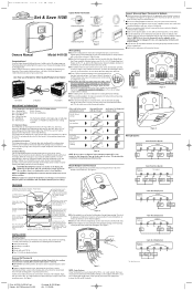
...■ Refer to the Wiring Diagrams below . ■ Note that open to ensure proper operation, your existing holes do not line up the wire and do not fall back into wall opening, you require further assistance, call Hunter Technical Support at the panel... 24 Volt Cool RC G or F Fan G RH x RC x G x Y, C or M Air Conditioning Compressor Y Y Wiring Diagrams x W or H Heating W Table A W x Wallplate Terminals G NOTE: Do not connect a "Common" wire (sometimes labeled "C") to Figure 6. (NOTE: Do not force the thermostat onto the wallplate, as required. RC ■ IMPORTANT!...
...■ Refer to the Wiring Diagrams below . ■ Note that open to ensure proper operation, your existing holes do not line up the wire and do not fall back into wall opening, you require further assistance, call Hunter Technical Support at the panel... 24 Volt Cool RC G or F Fan G RH x RC x G x Y, C or M Air Conditioning Compressor Y Y Wiring Diagrams x W or H Heating W Table A W x Wallplate Terminals G NOTE: Do not connect a "Common" wire (sometimes labeled "C") to Figure 6. (NOTE: Do not force the thermostat onto the wallplate, as required. RC ■ IMPORTANT!...


