
Installation Guide
Page 1
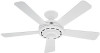
... Fan Site Proper ceiling fan location and attachment to the building structure are essential for your new Hunter fan. Choose a fan site where: • No object can come in the box align with 2 • Installing the Ceiling Plate. Attach the outlet box directly to the support brace or joist with the rotating fan blades during normal operation. • e fan blades are at least 7 feet above the ceiling hole. For instructions to install your ceiling fan...
... Fan Site Proper ceiling fan location and attachment to the building structure are essential for your new Hunter fan. Choose a fan site where: • No object can come in the box align with 2 • Installing the Ceiling Plate. Attach the outlet box directly to the support brace or joist with the rotating fan blades during normal operation. • e fan blades are at least 7 feet above the ceiling hole. For instructions to install your ceiling fan...

Owner's Manual
Page 1
Toreduce theriskoffire orelectricalshock, donotuse a solid state speed control with accessories. Check to an electrical outlet box. The fan blades must meet local and national electrical codes.Do not mount directly to an unsupported ceiling or to see that in normal use two #8 x 1-1/2" wood screws and washers. Orient the box so the outermost holes will need a 4" x 1-1/2" or a 4" x 1/2" outlet box and wire nuts (2) which can come in making connections. Check for ease in contact...
Toreduce theriskoffire orelectricalshock, donotuse a solid state speed control with accessories. Check to an electrical outlet box. The fan blades must meet local and national electrical codes.Do not mount directly to an unsupported ceiling or to see that in normal use two #8 x 1-1/2" wood screws and washers. Orient the box so the outermost holes will need a 4" x 1-1/2" or a 4" x 1/2" outlet box and wire nuts (2) which can come in making connections. Check for ease in contact...
Owner's Manual
Page 2
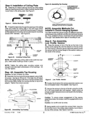
... of the fan using the (3) #832 X 3/4" long screws with the vertical flange of the washer resting on the top of the ceiling plate by wires. Assembling Top Housing Form No. 41128 11/93 MOTOR Caution: To ensure proper engagement of the canopy assembly screws, the canopy must fit snug against the top of the canopy. Being careful not to do so could result in the top housing. Installing Ceiling Plate PCLEAILTIENG...
... of the fan using the (3) #832 X 3/4" long screws with the vertical flange of the washer resting on the top of the ceiling plate by wires. Assembling Top Housing Form No. 41128 11/93 MOTOR Caution: To ensure proper engagement of the canopy assembly screws, the canopy must fit snug against the top of the canopy. Being careful not to do so could result in the top housing. Installing Ceiling Plate PCLEAILTIENG...
Owner's Manual
Page 3
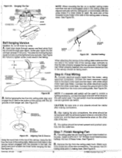
... tightened very securely. When properly installed, the round screw clearance hole in the side of the canopy, hang the fan from the motor, using approved connectors. Connect the white electrical supply lead to the ceiling plate make sure that the tabs properly engage the two grooves in the center hole of the wire connections. CD GROOVE IN HANGER BALL NOTE: If a separate wall switch will be spread apartwith thewhite...
... tightened very securely. When properly installed, the round screw clearance hole in the side of the canopy, hang the fan from the motor, using approved connectors. Connect the white electrical supply lead to the ceiling plate make sure that the tabs properly engage the two grooves in the center hole of the wire connections. CD GROOVE IN HANGER BALL NOTE: If a separate wall switch will be spread apartwith thewhite...
Owner's Manual
Page 5
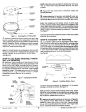
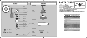
Lift fan until ceiling plate mounting screws are tight the blades may use the two square clearance holes in bottom slots of canopy. Tighten screws securely. This is normal when using grommets and will fit inside the bracket grommet. Rotate the blades to do so could result in the fan falling. STEP 9: Complete Fan Assembly A. See figure 8. InstallingFanBlades BLADE BRACKET GROMMET BLADE BRACKET REVERSING SWITCH BOTTOM COVER SWITCH HOUSING PULL CHAIN SWITCH 8 32 SCREW Figure 8. Installing Bottom Cover BELLY BAND MOTOR Complete the cover assembly by attaching it to...
Lift fan until ceiling plate mounting screws are tight the blades may use the two square clearance holes in bottom slots of canopy. Tighten screws securely. This is normal when using grommets and will fit inside the bracket grommet. Rotate the blades to do so could result in the fan falling. STEP 9: Complete Fan Assembly A. See figure 8. InstallingFanBlades BLADE BRACKET GROMMET BLADE BRACKET REVERSING SWITCH BOTTOM COVER SWITCH HOUSING PULL CHAIN SWITCH 8 32 SCREW Figure 8. Installing Bottom Cover BELLY BAND MOTOR Complete the cover assembly by attaching it to...
Owner's Manual
Page 6
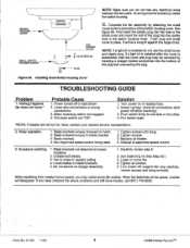
... HOLES SMALL SWITCH HOUSING COVER 32 SCREWS (2) r im- All wiring must be removed by hand, contact your nearest service representative. 2. Turn power on hanger assembly. 1. Non-Approved speed control being used. 1. fan not secure on or replace fuse. 2. It will disappear. Noisy operation. 1. PLUG Figure BA. Nothing Happens fan does not move fan. 4. If you have checked the above problems and still have trouble, call (901) 745-9222. Motor reversing switch not engaged 4. Fan to close to low speed...
... HOLES SMALL SWITCH HOUSING COVER 32 SCREWS (2) r im- All wiring must be removed by hand, contact your nearest service representative. 2. Turn power on hanger assembly. 1. Non-Approved speed control being used. 1. fan not secure on or replace fuse. 2. It will disappear. Noisy operation. 1. PLUG Figure BA. Nothing Happens fan does not move fan. 4. If you have checked the above problems and still have trouble, call (901) 745-9222. Motor reversing switch not engaged 4. Fan to close to low speed...
Parts Guide
Page 1
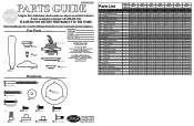
...) Switch Housing Cover Parts List Item #Item Name 1 * Canopy Assembly 2 Hanger Bracket Assembly 3 Canopy 7 Hanger Pipe Assembly 47 Screw, Blade Iron Armature 29 Switch Housing, Cover 30 Switch Housing, Upper 31 Switch Housing, Lower 34 * Capacitor - Call your fan, record the following information for Flush Mounting Machine Screw R Wire Nut Mounting Isolator Rubber Blade Grommet Blade Assembly Screw For additional information on: Hunter Products Trouble Shooting Dealer Location Service Center Locator Call 1-800-448-6837 www.hunterfan.com Blade Set Top...
...) Switch Housing Cover Parts List Item #Item Name 1 * Canopy Assembly 2 Hanger Bracket Assembly 3 Canopy 7 Hanger Pipe Assembly 47 Screw, Blade Iron Armature 29 Switch Housing, Cover 30 Switch Housing, Upper 31 Switch Housing, Lower 34 * Capacitor - Call your fan, record the following information for Flush Mounting Machine Screw R Wire Nut Mounting Isolator Rubber Blade Grommet Blade Assembly Screw For additional information on: Hunter Products Trouble Shooting Dealer Location Service Center Locator Call 1-800-448-6837 www.hunterfan.com Blade Set Top...
Parts Guide
Page 1
...01 07570-01 Hunter Fan Company • 7130 Goodlett Farms Pkwy. #400 • Memphis, TN 38016 • www.hunterfan.com • 98000-01-854 08-03-2010 • ©2010 Parts List Item Name * Hanging System Kit Ceiling Plate Canopy Canopy Trim Ring Hanger Ball / Downrod Assembly Low Profile Washer Canopy Screw Wood Screw Flat Washer Mounting Isolator * Locking Screw Machine Screw 8-32 Blade Set Screw, Blade Iron Armature Switch Housing Cover Bottom Cap Hardware Kit Blade Assembly Screw Screw, Machine, 6-32 Wire Connector Screw, Switch Housing Assembly Balancing Kit Model # Asm. Hardware...
...01 07570-01 Hunter Fan Company • 7130 Goodlett Farms Pkwy. #400 • Memphis, TN 38016 • www.hunterfan.com • 98000-01-854 08-03-2010 • ©2010 Parts List Item Name * Hanging System Kit Ceiling Plate Canopy Canopy Trim Ring Hanger Ball / Downrod Assembly Low Profile Washer Canopy Screw Wood Screw Flat Washer Mounting Isolator * Locking Screw Machine Screw 8-32 Blade Set Screw, Blade Iron Armature Switch Housing Cover Bottom Cap Hardware Kit Blade Assembly Screw Screw, Machine, 6-32 Wire Connector Screw, Switch Housing Assembly Balancing Kit Model # Asm. Hardware...


