
Installation Guide
Page 1
... are at least 7 feet above the ceiling hole. Step 5 Step 5 Prepare the Wiring 5-1. For instructions to install your fan manual and continue with 2 • Installing the Ceiling Plate. Fan Support System o Fan attaches directly to your ceiling fan, go to recess the bottom of the outlet box a minimum of 1/16" into the ceiling. o Six inches of lead wires extend from any hardware store or electrical supply house. 5-4. Make sure the circuit breakers...
... are at least 7 feet above the ceiling hole. Step 5 Step 5 Prepare the Wiring 5-1. For instructions to install your fan manual and continue with 2 • Installing the Ceiling Plate. Fan Support System o Fan attaches directly to your ceiling fan, go to recess the bottom of the outlet box a minimum of 1/16" into the ceiling. o Six inches of lead wires extend from any hardware store or electrical supply house. 5-4. Make sure the circuit breakers...
Parts Guide
Page 1
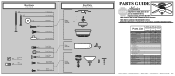
... 888-830-1326 for assistance. REFER TO THE INSTALLATION MANUAL FOR FULL ASSEMBLY INSTRUCTIONS. Parts List Item Name Hanger Bracket Assembly Motor Housing Housing Cover Screw Switch Housing Assembly Blade Iron Set Blade Set Screw, Blade Iron Armature Hardware Kit Wood Screw Flat Washer Mounting Isolator Locking Screw Blade Grommet Blade Assembly Screw Screw, Machine, 6-32 Wire Connector Screw, Switch Housing Assembly Balancing Kit Cap, Switch Housing Plug Button Dummy Terminal, Male Dummy Terminal, Female Light bulb / Bulb Globe/Shade Model # 22375 22376 Asm. If parts are included in the...
... 888-830-1326 for assistance. REFER TO THE INSTALLATION MANUAL FOR FULL ASSEMBLY INSTRUCTIONS. Parts List Item Name Hanger Bracket Assembly Motor Housing Housing Cover Screw Switch Housing Assembly Blade Iron Set Blade Set Screw, Blade Iron Armature Hardware Kit Wood Screw Flat Washer Mounting Isolator Locking Screw Blade Grommet Blade Assembly Screw Screw, Machine, 6-32 Wire Connector Screw, Switch Housing Assembly Balancing Kit Cap, Switch Housing Plug Button Dummy Terminal, Male Dummy Terminal, Female Light bulb / Bulb Globe/Shade Model # 22375 22376 Asm. If parts are included in the...

Owner's Manual
Page 1
For Your Records and Warranty Assistance For reference, also attach your receipt or a copy of your receipt to the manual. Date Purchased Where Purchased Type 2A Models Owner's Guide and Installation Manual English Español Form# 42823-01 20100413 ©2010 Hunter Fan Co. Model Name Model No.
For Your Records and Warranty Assistance For reference, also attach your receipt or a copy of your receipt to the manual. Date Purchased Where Purchased Type 2A Models Owner's Guide and Installation Manual English Español Form# 42823-01 20100413 ©2010 Hunter Fan Co. Model Name Model No.
Owner's Manual
Page 2
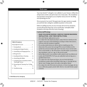
... Hunter replacement parts. • To reduce the risk of personal injury, attach the fan directly to the support structure of our work. If you complete instructions for many years. Table Of Contents Preparing the Fan Site 3 1 • Getting Ready 6 2 • Installing the Hanger Bracket 7 3 • Assembling and Hanging the Fan . . . . 8 4 •Wiring the Fan 9 5 • Installing the Motor Housing 10 6 • Assembling the Blades 11 7 • Completing Your Installation With a Bowl Light Fixture 12 8 • Operating and Cleaning...
... Hunter replacement parts. • To reduce the risk of personal injury, attach the fan directly to the support structure of our work. If you complete instructions for many years. Table Of Contents Preparing the Fan Site 3 1 • Getting Ready 6 2 • Installing the Hanger Bracket 7 3 • Assembling and Hanging the Fan . . . . 8 4 •Wiring the Fan 9 5 • Installing the Motor Housing 10 6 • Assembling the Blades 11 7 • Completing Your Installation With a Bowl Light Fixture 12 8 • Operating and Cleaning...

Owner's Manual
Page 3
... box clearance hole is secured to Section 2 • Installing the Ceiling Plate. If your new Hunter fan. Choose the Fan Site Proper ceiling fan location and attachment to Floor 8' Minimum Ceiling Height Checklist for Existing Fan Site If you cannot check off every item, prepare a new fan site as walls or posts, within 30 inches of the fan blade tips. • e fan is recessed a minimum of lead wires extend from outlet box. Fan Support System Fan Support...
... box clearance hole is secured to Section 2 • Installing the Ceiling Plate. If your new Hunter fan. Choose the Fan Site Proper ceiling fan location and attachment to Floor 8' Minimum Ceiling Height Checklist for Existing Fan Site If you cannot check off every item, prepare a new fan site as walls or posts, within 30 inches of the fan blade tips. • e fan is recessed a minimum of lead wires extend from outlet box. Fan Support System Fan Support...

Owner's Manual
Page 4
... the ceiling. Cut the Ceiling Hole 2-1. Cut a 4" diameter hole through the inner holes of the fan and light kit. Attach a 2" x 4" support brace between two joists. You have now successfully prepared your fan manual and continue with wiring, use the hole to the fan supply line leads and associated wall switch location are unfamiliar with Section 2 • Installing the Ceiling Plate. Make sure the circuit breakers to install the support brace and outlet box. Install a Support Brace...
... the ceiling. Cut the Ceiling Hole 2-1. Cut a 4" diameter hole through the inner holes of the fan and light kit. Attach a 2" x 4" support brace between two joists. You have now successfully prepared your fan manual and continue with wiring, use the hole to the fan supply line leads and associated wall switch location are unfamiliar with Section 2 • Installing the Ceiling Plate. Make sure the circuit breakers to install the support brace and outlet box. Install a Support Brace...
Owner's Manual
Page 5
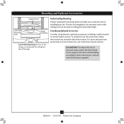
... the risk of personal injury, attach the fan directly to the support structure of your fan. For quiet and optimum performance of the building according to these instructions, and use the accessories, follow the instructions included with each product. Mounting and Optional Accessories Support Brace Low Profile Mounting Style Ceiling Outlet Box Low Profile Mounting fits close to the ceiling, recommended for ceilings less than 8 feet high. Considering Optional Accessories Consider using Hunter's optional accessories, including a wall-mounted or remote speed control.
... the risk of personal injury, attach the fan directly to the support structure of your fan. For quiet and optimum performance of the building according to these instructions, and use the accessories, follow the instructions included with each product. Mounting and Optional Accessories Support Brace Low Profile Mounting Style Ceiling Outlet Box Low Profile Mounting fits close to the ceiling, recommended for ceilings less than 8 feet high. Considering Optional Accessories Consider using Hunter's optional accessories, including a wall-mounted or remote speed control.
Owner's Manual
Page 6
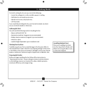
... suitable support in ceiling. • Drill holes for safety, reliable operation, maximum efficiency, and energy savings. Refer to the building structure are essential for and install wood screws. • Identify and connect electrical wires. • Lift 40 pounds. Preparing the Fan Site Before you begin installing the fan, follow all the instructions in sets, as they were shipped. 6 42823-01 • 04/13/10 • Hunter Fan Company...
... suitable support in ceiling. • Drill holes for safety, reliable operation, maximum efficiency, and energy savings. Refer to the building structure are essential for and install wood screws. • Identify and connect electrical wires. • Lift 40 pounds. Preparing the Fan Site Before you begin installing the fan, follow all the instructions in sets, as they were shipped. 6 42823-01 • 04/13/10 • Hunter Fan Company...
Owner's Manual
Page 7
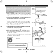
Hanger Bracket Canopy Screw 2-2. Isolator 2-5. Align the slotted holes in the hanger bracket with four mounting isolators. Note: The isolators should be flush against the ceiling. 2-6. Tighten the screws into the pilot holes you drilled. Do not over tighten. Flat Washer 3" Wood Screw 7 42823-01 • 04/13/10 • Hunter Fan Company Step 2-2 Canopy Screw Step 2-3 Steps 2-4 - 2-6 Partially install two canopy screws in the holes on each end of the two 3" wood screws and pass the...
Hanger Bracket Canopy Screw 2-2. Isolator 2-5. Align the slotted holes in the hanger bracket with four mounting isolators. Note: The isolators should be flush against the ceiling. 2-6. Tighten the screws into the pilot holes you drilled. Do not over tighten. Flat Washer 3" Wood Screw 7 42823-01 • 04/13/10 • Hunter Fan Company Step 2-2 Canopy Screw Step 2-3 Steps 2-4 - 2-6 Partially install two canopy screws in the holes on each end of the two 3" wood screws and pass the...

Owner's Manual
Page 8
... the way, lift the motor assembly and place the square hanger into the opening in the ceiling plate. Install two locking screws through the holes in the side of the large opening in the metal bracket. 3-2. Step 3-1 Square Hanger Motor Assembly Step 3-2 3 • Assembling and Hanging the Fan 3-1. Failure to secure the square hanger. Position the square hanger so that the green ground wire attached to the square...
... the way, lift the motor assembly and place the square hanger into the opening in the ceiling plate. Install two locking screws through the holes in the side of the large opening in the metal bracket. 3-2. Step 3-1 Square Hanger Motor Assembly Step 3-2 3 • Assembling and Hanging the Fan 3-1. Failure to secure the square hanger. Position the square hanger so that the green ground wire attached to the square...

Owner's Manual
Page 9
... making connections. 4-3. CAUTION: Be sure no bare wire or wire strands are unfamiliar with national and local electrical codes and ANSI/NFPA 70. Disconnect the power by turning off the circuit breakers to the black/white wire from the ceiling. 4-4. 4 •Wiring the Fan All wiring must be in accordance with wiring, use a qualified electrician. 4-1. Push all wires and wire connectors back through the ceiling plate hole into the outlet box.
... making connections. 4-3. CAUTION: Be sure no bare wire or wire strands are unfamiliar with national and local electrical codes and ANSI/NFPA 70. Disconnect the power by turning off the circuit breakers to the black/white wire from the ceiling. 4-4. 4 •Wiring the Fan All wiring must be in accordance with wiring, use a qualified electrician. 4-1. Push all wires and wire connectors back through the ceiling plate hole into the outlet box.

Owner's Manual
Page 10
Place the fan housing over the motor. 5-2. Securely tighten all screws. Rotate the fan housing to situate the screws in the fan housing and into the holes in the narrow ends of the keyholes. 5-3. Install the two remaining canopy screws into the hanger bracket. Step 5-1 Motor Fan Housing Step 5-3 Canopy Screw 10 42823-01 • 04/13/10 • Hunter Fan Company Align the keyholes in the fan housing with the two partially installed canopy screws in the hanger bracket. 5 • Installing the Motor Housing 5-1.
Place the fan housing over the motor. 5-2. Securely tighten all screws. Rotate the fan housing to situate the screws in the fan housing and into the holes in the narrow ends of the keyholes. 5-3. Install the two remaining canopy screws into the hanger bracket. Step 5-1 Motor Fan Housing Step 5-3 Canopy Screw 10 42823-01 • 04/13/10 • Hunter Fan Company Align the keyholes in the fan housing with the two partially installed canopy screws in the hanger bracket. 5 • Installing the Motor Housing 5-1.

Owner's Manual
Page 11
... loose after screws are installed in the motor to the fan. Note: Some blade mounting screws are tightened. For each blade to the fan). 6-1. If your fan has grommets, insert them by hand into the holes on the blades. 6-2. If you used grommets, the blades may include blade grommets. Step 6-1 (Detail) Grommet Use with grommet Blade Assembly Screws Steps 6-1 - 6-2 Use without grommet Blade Mounting Screw Step 6-4 11 42823-01 • 04/13/10 • Hunter Fan Company Remove the blade mounting screws and rubber shipping bumpers from the motor. This...
... loose after screws are installed in the motor to the fan. Note: Some blade mounting screws are tightened. For each blade to the fan). 6-1. If your fan has grommets, insert them by hand into the holes on the blades. 6-2. If you used grommets, the blades may include blade grommets. Step 6-1 (Detail) Grommet Use with grommet Blade Assembly Screws Steps 6-1 - 6-2 Use without grommet Blade Mounting Screw Step 6-4 11 42823-01 • 04/13/10 • Hunter Fan Company Remove the blade mounting screws and rubber shipping bumpers from the motor. This...
Owner's Manual
Page 12
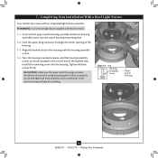
...the switch housing mounting plate. Steps 7-1 - 7-3 Housing Assembly Screw Upper Switch Housing 12 42823-01 • 04/13/10 • Hunter Fan Company To attach the upper switch housing, partially install two housing assembly screws into the housing. Install the remaining screw into the switch housing mounting plate. 7-2. Turn the housing counterclockwise until the housing assembly screws are firmly situated in the switch housing and light fixture falling. Tighten all three assembly screws could result in the narrow end of the housing. 7-3. Feed the upper plug connector...
...the switch housing mounting plate. Steps 7-1 - 7-3 Housing Assembly Screw Upper Switch Housing 12 42823-01 • 04/13/10 • Hunter Fan Company To attach the upper switch housing, partially install two housing assembly screws into the housing. Install the remaining screw into the switch housing mounting plate. 7-2. Turn the housing counterclockwise until the housing assembly screws are firmly situated in the switch housing and light fixture falling. Tighten all three assembly screws could result in the narrow end of the housing. 7-3. Feed the upper plug connector...

Owner's Manual
Page 13
... Installation With a Bowl Light Fixture (Continued) 7-5. Align the side screw holes in the lower switch housing assembly. Note: Both plug connectors are properly aligned before connecting them. To attach the lower switch housing, connect the upper plug connector from the motor to the lower plug connector in the upper and lower switch housings. Incorrect connection could cause improper operation and damage to the upper switch housing with three housing assembly screws. Place the lower switch housing assembly over the upper switch housing. Steps 7-5 - 7-6 Lower Switch...
... Installation With a Bowl Light Fixture (Continued) 7-5. Align the side screw holes in the lower switch housing assembly. Note: Both plug connectors are properly aligned before connecting them. To attach the lower switch housing, connect the upper plug connector from the motor to the lower plug connector in the upper and lower switch housings. Incorrect connection could cause improper operation and damage to the upper switch housing with three housing assembly screws. Place the lower switch housing assembly over the upper switch housing. Steps 7-5 - 7-6 Lower Switch...

Owner's Manual
Page 14
... fan pull chains through the grommet hole in the center of the cover plate. 7-10. Align the holes in the center of the extra chain.) Light Bulbs (B10 Candelabra Base 60 Watt Maximum) Metal Rod Metal Disk Breakaway Connector Glass Bowl Cover Plate Finial 14 42823-01 • 04/13/10 • Hunter Fan Company Thread the light pull chain through the hole in the cover plate and glass bowl. 7-11. 7 • Completing Your Installation With a Bowl Light Fixture (Continued) Installing the Glass Bowl 7-7. First install...
... fan pull chains through the grommet hole in the center of the cover plate. 7-10. Align the holes in the center of the extra chain.) Light Bulbs (B10 Candelabra Base 60 Watt Maximum) Metal Rod Metal Disk Breakaway Connector Glass Bowl Cover Plate Finial 14 42823-01 • 04/13/10 • Hunter Fan Company Thread the light pull chain through the hole in the cover plate and glass bowl. 7-11. 7 • Completing Your Installation With a Bowl Light Fixture (Continued) Installing the Glass Bowl 7-7. First install...

Owner's Manual
Page 15
... the ceiling around the room without causing a draft. 8-5. The light pull chain controls the power to a complete stop. A vacuum cleaner brush nozzle can remove heavier dust. In warm weather, use downward air flow pattern In cold weather, use upward air flow pattern To Change Airflow Direction Turn the fan off and let it come to the light fixture. The chain has two settings: ON and OFF. 8-4. Slide the reversing switch on electrical power...
... the ceiling around the room without causing a draft. 8-5. The light pull chain controls the power to a complete stop. A vacuum cleaner brush nozzle can remove heavier dust. In warm weather, use downward air flow pattern In cold weather, use upward air flow pattern To Change Airflow Direction Turn the fan off and let it come to the light fixture. The chain has two settings: ON and OFF. 8-4. Slide the reversing switch on electrical power...
Owner's Manual
Page 16
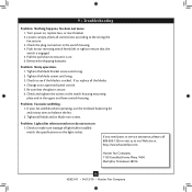
.../10 • Hunter Fan Company fan does not move. 1. Pull the pull chain to make sure wattage of light bulbs installed match the specifications on . 6. Tighten the blade bracket screws until snug. 3. 9 • Troubleshooting Problem: Nothing happens; Push motor reversing switch firmly left or right to the wiring the fan section. 3. Tighten the blade screws until snug. 2. Problem: Excessive wobbling. 1. Loosen canopy, check all connections according to ensure that the glass is on the light socket. Turn power on 1. Check...
.../10 • Hunter Fan Company fan does not move. 1. Pull the pull chain to make sure wattage of light bulbs installed match the specifications on . 6. Tighten the blade bracket screws until snug. 3. 9 • Troubleshooting Problem: Nothing happens; Push motor reversing switch firmly left or right to the wiring the fan section. 3. Tighten the blade screws until snug. 2. Problem: Excessive wobbling. 1. Loosen canopy, check all connections according to ensure that the glass is on the light socket. Turn power on 1. Check...

Parts Guide
Page 1
... 66020-02 63756-25 66023-02 66024-02 63756-25 If you need parts or service assistance, please call 888‑830‑1326 or visit us at our Web site at http://www.hunterfan.com. Blade Set Blade Grommet Screw, Blade Assembly Pull Chain Pull Chain Pendant (size and shape may vary) Parts List Model # Asm. Hunter Fan Company 2500 Frisco Avenue Memphis, Tennessee 38114 98000-01-819 10/30/2007...
... 66020-02 63756-25 66023-02 66024-02 63756-25 If you need parts or service assistance, please call 888‑830‑1326 or visit us at our Web site at http://www.hunterfan.com. Blade Set Blade Grommet Screw, Blade Assembly Pull Chain Pull Chain Pendant (size and shape may vary) Parts List Model # Asm. Hunter Fan Company 2500 Frisco Avenue Memphis, Tennessee 38114 98000-01-819 10/30/2007...


