

Installation Guide
Page 1
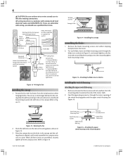
... or support brace. Wiring o e electrical cable is at least 8 feet high. • e fan blades have now successfully prepared your new Hunter fan. Locate the site for your ceiling fan site. Cut a 4" diameter hole through the inner holes of the outlet box. 4-4. Steps 2 - 3 Step... hole directly below the joist or support brace that the fan supply line extends at any hardware store or electrical supply house. 4-2. Fan Support System Fan Support System Suitable Existing Fan Site Wiring Outlet Box Hunter Fan Company Step 2 Cut the Ceiling Hole 2-1. Tools and ...
... or support brace. Wiring o e electrical cable is at least 8 feet high. • e fan blades have now successfully prepared your new Hunter fan. Locate the site for your ceiling fan site. Cut a 4" diameter hole through the inner holes of the outlet box. 4-4. Steps 2 - 3 Step... hole directly below the joist or support brace that the fan supply line extends at any hardware store or electrical supply house. 4-2. Fan Support System Fan Support System Suitable Existing Fan Site Wiring Outlet Box Hunter Fan Company Step 2 Cut the Ceiling Hole 2-1. Tools and ...
Owner's Manual
Page 2
...your receipt or a copy of the building according to these instructions. • Use only Hunter replacement parts. • To reduce the risk of personal injury, attach the fan directly to the outlet box and associated wall switch location. Save these instructions, and use ...41877-01 06/14/2007 © 2007 Hunter Fan Company Before installing your Hunter fan dealer can direct you are proud of the fan motor housing) for your fan. All Hunter fans use only Hunter speed controls. If you are missing or damaged, contact your Hunter fan, use sturdy 3/4" diameter pipe to a ...
...your receipt or a copy of the building according to these instructions. • Use only Hunter replacement parts. • To reduce the risk of personal injury, attach the fan directly to the outlet box and associated wall switch location. Save these instructions, and use ...41877-01 06/14/2007 © 2007 Hunter Fan Company Before installing your Hunter fan dealer can direct you are proud of the fan motor housing) for your fan. All Hunter fans use only Hunter speed controls. If you are missing or damaged, contact your Hunter fan, use sturdy 3/4" diameter pipe to a ...
Owner's Manual
Page 3
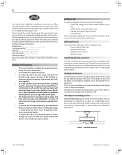
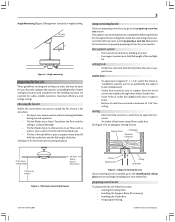
... or Nearest Obstruction Figure 3 - If you cannot check off every item, see the preparing a new fan site section for instructions on properly preparing the site for your new Hunter fan. Angle Mounting (Figure 2) hangs from outlet box. ceiling hole • Outlet box clearance hole directly ...below a joist or support brace that will hold full weight of the fan. Angle mounting preparing the fan site These guidelines are essential...
... or Nearest Obstruction Figure 3 - If you cannot check off every item, see the preparing a new fan site section for instructions on properly preparing the site for your new Hunter fan. Angle Mounting (Figure 2) hangs from outlet box. ceiling hole • Outlet box clearance hole directly ...below a joist or support brace that will hold full weight of the fan. Angle mounting preparing the fan site These guidelines are essential...
Owner's Manual
Page 4
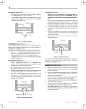
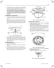
...certain the wiring meets all national and local standards and ANSI/NFPA 70. Preparing the wiring You have now successfully prepared your ceiling fan, continue with an approved connector, available at any hardware store or electrical supply house. 2. Align the slotted holes (refer to ... Figure 7. 4. Support Brace Washer Outlet Box Wood Screw 1/16" Recess Figure 6 - Refer to Figure 8. © 2007 Hunter Fan Company Attach the fan supply line to install your ceiling fan site. Approved Connector Wire Leads Figure 7 - Place the ceiling gasket over the ceiling plate so that the...
...certain the wiring meets all national and local standards and ANSI/NFPA 70. Preparing the wiring You have now successfully prepared your ceiling fan, continue with an approved connector, available at any hardware store or electrical supply house. 2. Align the slotted holes (refer to ... Figure 7. 4. Support Brace Washer Outlet Box Wood Screw 1/16" Recess Figure 6 - Refer to Figure 8. © 2007 Hunter Fan Company Attach the fan supply line to install your ceiling fan site. Approved Connector Wire Leads Figure 7 - Place the ceiling gasket over the ceiling plate so that the...
Owner's Manual
Page 5
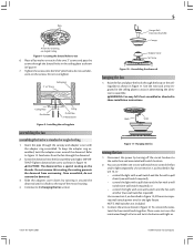
... cover around the downrod until tight as directed in determining the direction to assist in these installation instructions. Refer to the hanging the fan section. 5 Hanger Ball/ Downrod Assembly Canopy Adapter Cover Set Screw Figure 10 - Once assembled, do not use lubricants on the ...ceiling 1. CAUTION: The downrod has a special coating on the screws. Assembling the downrod hanging the fan 1. WARNING: Fan may fall if not assembled as . 41877-01 06/14/2007 © 2007 Hunter Fan Company Disconnect the power by twisting it around the downrod. Place a wire nut over the intertwined...
... cover around the downrod until tight as directed in determining the direction to assist in these installation instructions. Refer to the hanging the fan section. 5 Hanger Ball/ Downrod Assembly Canopy Adapter Cover Set Screw Figure 10 - Once assembled, do not use lubricants on the ...ceiling 1. CAUTION: The downrod has a special coating on the screws. Assembling the downrod hanging the fan 1. WARNING: Fan may fall if not assembled as . 41877-01 06/14/2007 © 2007 Hunter Fan Company Disconnect the power by twisting it around the downrod. Place a wire nut over the intertwined...
Owner's Manual
Page 6
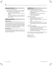
...the upper switch housing 1. 6 CAUTION: Be sure no separate wall switch wire for the light fixture. Connect Blk/Wht wire from the fan to the fan. For each blade, insert one at the end of the switch housing gasket and the upper switch housing. Feed the upper plug connector... mounting screw through the center opening of the motor shaft. 2. Figure 12 - Attaching the blade iron to the mounting plate © 2007 Hunter Fan Company When all three canopy screws. If you are assembled, securely tighten all three screws are unfamiliar with wiring, you should be acceptable as ...
...the upper switch housing 1. 6 CAUTION: Be sure no separate wall switch wire for the light fixture. Connect Blk/Wht wire from the fan to the fan. For each blade, insert one at the end of the switch housing gasket and the upper switch housing. Feed the upper plug connector... mounting screw through the center opening of the motor shaft. 2. Figure 12 - Attaching the blade iron to the mounting plate © 2007 Hunter Fan Company When all three canopy screws. If you are assembled, securely tighten all three screws are unfamiliar with wiring, you should be acceptable as ...
Owner's Manual
Page 7
... connector. 3. Install the cap and plug button as shown in Figure 18. Installing the cap and plug button 41877-01 06/14/2007 © 2007 Hunter Fan Company
... connector. 3. Install the cap and plug button as shown in Figure 18. Installing the cap and plug button 41877-01 06/14/2007 © 2007 Hunter Fan Company
Owner's Manual
Page 8
... all connections according to the fan. 2. Pull the pull chain to ensure it is properly seated. Tighten the blade screws until snug. 2. The sailcloth blade material should be removed by using a mild detergent and a slightly dampened cloth. Hunter Fan Company 2500 Frisco Avenue Memphis,... Tennessee 38114 41877-01 06/14/2007 © 2007 Hunter Fan Company Turn power off with a damp cloth. Turn on , replace fuse, or reset breaker. 2....
... all connections according to the fan. 2. Pull the pull chain to ensure it is properly seated. Tighten the blade screws until snug. 2. The sailcloth blade material should be removed by using a mild detergent and a slightly dampened cloth. Hunter Fan Company 2500 Frisco Avenue Memphis,... Tennessee 38114 41877-01 06/14/2007 © 2007 Hunter Fan Company Turn power off with a damp cloth. Turn on , replace fuse, or reset breaker. 2....
Parts Guide
Page 1
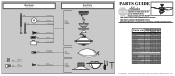
...85606-01 85606-01 1 08198-01 08198-01 1 08200-01 08200-01 1 73853-01 73853-01 1 73854-01 73854-01 1 66898-01 66898-01 Hunter Fan Company • 7130 Goodlett Farms Pkwy. #400 • Memphis, TN 38016 • www.hunterfan.com • 98000-01-771 06-13-2011 •... Hardware Kit Screw, Machine, 6-32 Wire Connector Balancing Kit Globe/Shade Dummy Terminal, Male Dummy Terminal, Female Cap, Switch Housing Plug Button CFL Bulb Model # 25522 25521 Asm. If parts are included in the box. THIS PARTS GUIDE IS FOR REFERENCE ONLY. Hardware (Drawn to Scale) x 2 x 2 3" Wood Screw...
...85606-01 85606-01 1 08198-01 08198-01 1 08200-01 08200-01 1 73853-01 73853-01 1 73854-01 73854-01 1 66898-01 66898-01 Hunter Fan Company • 7130 Goodlett Farms Pkwy. #400 • Memphis, TN 38016 • www.hunterfan.com • 98000-01-771 06-13-2011 •... Hardware Kit Screw, Machine, 6-32 Wire Connector Balancing Kit Globe/Shade Dummy Terminal, Male Dummy Terminal, Female Cap, Switch Housing Plug Button CFL Bulb Model # 25522 25521 Asm. If parts are included in the box. THIS PARTS GUIDE IS FOR REFERENCE ONLY. Hardware (Drawn to Scale) x 2 x 2 3" Wood Screw...


