
Installation Guide
Page 1
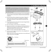
... the floor and the ceiling is suitable, go to your new Hunter fan. If NOT, install a support brace as specified by an approved connector. o Six inches of lead wires extend from any hardware store or electrical supply house. 5-4. Cut a 4" diameter hole through the inner holes of the ceiling. Make sure the circuit breakers to the fan supply line leads and associated wall switch location are aligned with 2 • Installing the Ceiling Plate...
... the floor and the ceiling is suitable, go to your new Hunter fan. If NOT, install a support brace as specified by an approved connector. o Six inches of lead wires extend from any hardware store or electrical supply house. 5-4. Cut a 4" diameter hole through the inner holes of the ceiling. Make sure the circuit breakers to the fan supply line leads and associated wall switch location are aligned with 2 • Installing the Ceiling Plate...

Owner's Manual
Page 1
For Your Records and Warranty Assistance Model Name Catalog/Model No Serial No Date Purchased Where Purchased For reference also attach your receipt or a copy of your receipt to the manual. 42405-01 • 01/20/06
For Your Records and Warranty Assistance Model Name Catalog/Model No Serial No Date Purchased Where Purchased For reference also attach your receipt or a copy of your receipt to the manual. 42405-01 • 01/20/06
Owner's Manual
Page 2
... Ready 4 2 • Installing the Ceiling Plate 5 3 • Assembling and Hanging the Fan..........6 4 • Wiring the Fan 7 5 • Installing the Canopy 8 6 • Assembling the Blades 9 7 • Installing the Switch Housing 10 8 • Operating and Cleaning Your Ceiling Fan 11 9 • Troubleshooting 12 © 2006 Hunter Fan Company Hunter Fan Company Your new Hunter® ceiling fan is an addition to your home or office that will provide comfort and performance for many years. is installation and operation manual gives you complete instructions for your...
... Ready 4 2 • Installing the Ceiling Plate 5 3 • Assembling and Hanging the Fan..........6 4 • Wiring the Fan 7 5 • Installing the Canopy 8 6 • Assembling the Blades 9 7 • Installing the Switch Housing 10 8 • Operating and Cleaning Your Ceiling Fan 11 9 • Troubleshooting 12 © 2006 Hunter Fan Company Hunter Fan Company Your new Hunter® ceiling fan is an addition to your home or office that will provide comfort and performance for many years. is installation and operation manual gives you complete instructions for your...
Owner's Manual
Page 3
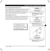
... manual include instructions for all three Installer's Choice mounting methods. For quiet and optimum performance of three ways, depending on ceiling height and your Hunter fan, use only Hunter speed controls. Considering Optional Accessories Consider using Hunter's optional accessories, including a wall-mounted or remote speed control. Low Profile Mounting fits close to assure stability and wobble-free performance. To install and use sturdy 3/4" diameter pipe to the ceiling, recommended for a vaulted or angled ceiling Hunter Fan Company Standard Mounting hangs from the ceiling...
... manual include instructions for all three Installer's Choice mounting methods. For quiet and optimum performance of three ways, depending on ceiling height and your Hunter fan, use only Hunter speed controls. Considering Optional Accessories Consider using Hunter's optional accessories, including a wall-mounted or remote speed control. Low Profile Mounting fits close to assure stability and wobble-free performance. To install and use sturdy 3/4" diameter pipe to the ceiling, recommended for a vaulted or angled ceiling Hunter Fan Company Standard Mounting hangs from the ceiling...
Owner's Manual
Page 4
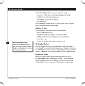
... Hunter fan dealer can do the following: • Locate the ceiling joist or other suitable support in sets, as they were shipped. To install a ceiling fan, be sure you begin installing the fan, follow all the instructions in the pullout sheet called "Preparing the Fan Site." Check for any parts are installing more than one fan, keep the fan blades and blade irons (if applicable) in ceiling. • Drill holes for safety, reliable operation...
... Hunter fan dealer can do the following: • Locate the ceiling joist or other suitable support in sets, as they were shipped. To install a ceiling fan, be sure you begin installing the fan, follow all the instructions in the pullout sheet called "Preparing the Fan Site." Check for any parts are installing more than one fan, keep the fan blades and blade irons (if applicable) in ceiling. • Drill holes for safety, reliable operation...
Owner's Manual
Page 5
... ceiling plate with two neoprene noise isolators ("Isolators"). Note: e isolators should be flush against the ceiling. 2-6. 2 • Installing the Ceiling Plate CAUTION: To avoid possible electrical shock, before installing your fan, disconnect the power by inserting the raised areas on each of the ceiling plate. 2-4. Tighten the screws into the holes in the ceiling plate. 2-3. read the lead wires from each other. Do not over tighten. do not use slotted holes directly...
... ceiling plate with two neoprene noise isolators ("Isolators"). Note: e isolators should be flush against the ceiling. 2-6. 2 • Installing the Ceiling Plate CAUTION: To avoid possible electrical shock, before installing your fan, disconnect the power by inserting the raised areas on each of the ceiling plate. 2-4. Tighten the screws into the holes in the ceiling plate. 2-3. read the lead wires from each other. Do not over tighten. do not use slotted holes directly...
Owner's Manual
Page 6
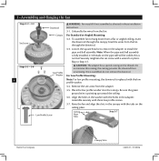
... align the slots in these installation instructions. 3-1. Feed the wires from the adapter. 3-5. Loosen the square head set screw on the ceiling plate. Once assembled, do not remove the downrod. Canopy For Standard or Angled Mounting: Set Screw 3-2. Securely retighten the set screw from the fan through the canopy. For Low Profile Mounting: 6 Note: For low profile mounting, the downrod is fully installed, 2-3 threads on the threads. this coating; Low Profile Screw Ceiling Plate Tabs Step 3-7 Hunter Fan Company Canopy Slots 42405-01 • 01/20...
... align the slots in these installation instructions. 3-1. Feed the wires from the adapter. 3-5. Loosen the square head set screw on the ceiling plate. Once assembled, do not remove the downrod. Canopy For Standard or Angled Mounting: Set Screw 3-2. Securely retighten the set screw from the fan through the canopy. For Low Profile Mounting: 6 Note: For low profile mounting, the downrod is fully installed, 2-3 threads on the threads. this coating; Low Profile Screw Ceiling Plate Tabs Step 3-7 Hunter Fan Company Canopy Slots 42405-01 • 01/20...
Owner's Manual
Page 7
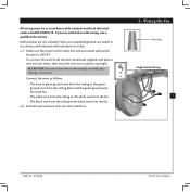
... local electrical codes and ANSI/NFPA 70. Wall switches are visible after making connections. Make sure the power to the black wire from the fan 4-2. Push all wires and wire nuts into the outlet box. 4 • Wiring the Fan Wire Nut Single Switch Wiring 7 42405-01 • 01/20/06 Hunter Fan Company Connect the wires as follows: • e bare or green ground wire from the ceiling to the green ground wire from the ceiling plate...
... local electrical codes and ANSI/NFPA 70. Wall switches are visible after making connections. Make sure the power to the black wire from the fan 4-2. Push all wires and wire nuts into the outlet box. 4 • Wiring the Fan Wire Nut Single Switch Wiring 7 42405-01 • 01/20/06 Hunter Fan Company Connect the wires as follows: • e bare or green ground wire from the ceiling to the green ground wire from the ceiling plate...
Owner's Manual
Page 8
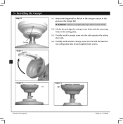
... screws. 8 Step 5-3 Step 5-4 Hunter Fan Company 42405-01 • 01/20/06 5 • Installing the Canopy Step 5-1 Tab Groove Step 5-2 5-1. Rotate the hanger ball so the tab in the canopy is secure in the groove in the hanger ball. WARNING: Failure to complete this step could cause fan to fall. 5-2. Lift the fan and align the canopy screw holes with the mounting holes on the ceiling plate. 5-3. Partially install a canopy screw...
... screws. 8 Step 5-3 Step 5-4 Hunter Fan Company 42405-01 • 01/20/06 5 • Installing the Canopy Step 5-1 Tab Groove Step 5-2 5-1. Rotate the hanger ball so the tab in the canopy is secure in the groove in the hanger ball. WARNING: Failure to complete this step could cause fan to fall. 5-2. Lift the fan and align the canopy screw holes with the mounting holes on the ceiling plate. 5-3. Partially install a canopy screw...
Owner's Manual
Page 9
Remove the blade mounting screws and rubber bumpers from the motor. If your fan has grommets, insert them by hand into the holes on the blades. 6-2. If you used grommets, the blades may include blade grommets. Save the screws and discard the bumpers. 6-4. Use with grommet Blade Assembly Steps 6-1 - 6-2 Screws 6 • Assembling the Blades Step 6-1 (Detail) Grommet 9 Use without grommet Blade Mounting Screw 42405-01 • 01/20/06 Step 6-4 Hunter Fan Company Your fan may appear slightly loose after screws are installed in the motor to the fan). 6-1. Some...
Remove the blade mounting screws and rubber bumpers from the motor. If your fan has grommets, insert them by hand into the holes on the blades. 6-2. If you used grommets, the blades may include blade grommets. Save the screws and discard the bumpers. 6-4. Use with grommet Blade Assembly Steps 6-1 - 6-2 Screws 6 • Assembling the Blades Step 6-1 (Detail) Grommet 9 Use without grommet Blade Mounting Screw 42405-01 • 01/20/06 Step 6-4 Hunter Fan Company Your fan may appear slightly loose after screws are installed in the motor to the fan). 6-1. Some...
Owner's Manual
Page 10
...only fit together one way. Attach the lower switch housing to the product. Failure to properly attach and tighten all three screws firmly. Plug Connector 7-6. Place the lower switch housing assembly over the upper switch housing. Align the side screw holes in the switch housing fixture falling. 7-5. To attach the upper switch housing, partially install two housing assembly screws into the housing. Install the remaining housing assembly screw into the switch housing mounting plate. 7-2. Lower Switch Housing Housing Assembly Screw Steps 7-5 - 7-6 Hunter Fan Company 42405...
...only fit together one way. Attach the lower switch housing to the product. Failure to properly attach and tighten all three screws firmly. Plug Connector 7-6. Place the lower switch housing assembly over the upper switch housing. Align the side screw holes in the switch housing fixture falling. 7-5. To attach the upper switch housing, partially install two housing assembly screws into the housing. Install the remaining housing assembly screw into the switch housing mounting plate. 7-2. Lower Switch Housing Housing Assembly Screw Steps 7-5 - 7-6 Hunter Fan Company 42405...
Owner's Manual
Page 11
... the connector. 8-3. e light pull chain controls power to prevent scratching. Restart fan. Reversing Switch 42405-01 • 01/20/06 Hunter Fan Company A vacuum cleaner brush nozzle can remove heavier dust. Turn on the fan to cool the room with a furniture polishing cloth. Ceiling fans work best by blowing air downward (counterclockwise blade rotation) in warm weather to the opposite position. Clean wood finish blades with a direct breeze. Clean painted and high-gloss blades in sequence: High, Medium, Low...
... the connector. 8-3. e light pull chain controls power to prevent scratching. Restart fan. Reversing Switch 42405-01 • 01/20/06 Hunter Fan Company A vacuum cleaner brush nozzle can remove heavier dust. Turn on the fan to cool the room with a furniture polishing cloth. Ceiling fans work best by blowing air downward (counterclockwise blade rotation) in warm weather to the opposite position. Clean wood finish blades with a direct breeze. Clean painted and high-gloss blades in sequence: High, Medium, Low...
Owner's Manual
Page 12
... plug connection in the switch housing. 4. Problem: Noisy operation. 1. Tighten the blade bracket screws until snug. 2. If so, replace all blade iron screws. 3. Push motor reversing switch firmly up or down to balance the fan. 2. Hunter Fan Company 2500 Frisco Avenue Memphis, Tennessee 38114 Hunter Fan Company 42405-01 • 01/20/06 Remove the shipping bumpers. If you need parts or service assistance, please call 888-830-1326 or visit us at our Web site at http://www.hunterfan...
... plug connection in the switch housing. 4. Problem: Noisy operation. 1. Tighten the blade bracket screws until snug. 2. If so, replace all blade iron screws. 3. Push motor reversing switch firmly up or down to balance the fan. 2. Hunter Fan Company 2500 Frisco Avenue Memphis, Tennessee 38114 Hunter Fan Company 42405-01 • 01/20/06 Remove the shipping bumpers. If you need parts or service assistance, please call 888-830-1326 or visit us at our Web site at http://www.hunterfan...
Parts Guide
Page 1
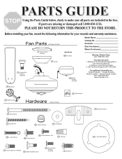
... on: Hunter Products Trouble Shooting Dealer Location Service Center Locator Call 1-800-448-6837 www.hunterfan.com 46 Blade Set Motor Housing Assembly 75 Balancing Kit 44 Blade Iron Set Hardware (Drawn to Scale) Hanger Bracket Assembly 78 Pull Chain Model Name Catalog No. Fan Parts (Not Drawn to Scale) 65 Wood Screw 71 Mounting Isolator 64 Wood Screw 66 Blade Grommet 68 Flat Washer 100 Locking Screw 62 Canopy Screw 69 Screw, Machine, 6-32 70 Wire Nut 47 Screw, Blade Iron Armature 67 Blade Assembly Screw 131 Screw, Switch Housing Assembly 8 Setscrew 27 Low Profile Washer...
... on: Hunter Products Trouble Shooting Dealer Location Service Center Locator Call 1-800-448-6837 www.hunterfan.com 46 Blade Set Motor Housing Assembly 75 Balancing Kit 44 Blade Iron Set Hardware (Drawn to Scale) Hanger Bracket Assembly 78 Pull Chain Model Name Catalog No. Fan Parts (Not Drawn to Scale) 65 Wood Screw 71 Mounting Isolator 64 Wood Screw 66 Blade Grommet 68 Flat Washer 100 Locking Screw 62 Canopy Screw 69 Screw, Machine, 6-32 70 Wire Nut 47 Screw, Blade Iron Armature 67 Blade Assembly Screw 131 Screw, Switch Housing Assembly 8 Setscrew 27 Low Profile Washer...
Parts Guide
Page 2
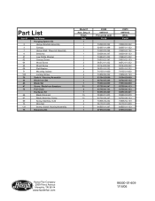
Part List Item # 2 3 7 8 27 62 64 65 68 71 100 28 44 46 47 78 66 67 69 70 131 75 Item Name Hanging System Kit Hanger Bracket Assembly Canopy Hanger Ball / Downrod Assembly Setscrew Low Profile Washer Canopy Screw Wood Screw Wood Screw Flat Washer Mounting Isolator Locking Screw Switch / Housing Assembly Blade Iron Set Blade Set Screw, Blade Iron Armature Pull Chain Hardware Kit Blade Grommet Blade Assembly Screw Screw, Machine, 6-32 Wire Nut Screw, Switch Housing Assembly Balancing Kit Model # Asm...01-000 64555-01-247 07570-01-000 23979 94956-02 White Part # 74090-02-232 92697-01-132 74229...
Part List Item # 2 3 7 8 27 62 64 65 68 71 100 28 44 46 47 78 66 67 69 70 131 75 Item Name Hanging System Kit Hanger Bracket Assembly Canopy Hanger Ball / Downrod Assembly Setscrew Low Profile Washer Canopy Screw Wood Screw Wood Screw Flat Washer Mounting Isolator Locking Screw Switch / Housing Assembly Blade Iron Set Blade Set Screw, Blade Iron Armature Pull Chain Hardware Kit Blade Grommet Blade Assembly Screw Screw, Machine, 6-32 Wire Nut Screw, Switch Housing Assembly Balancing Kit Model # Asm...01-000 64555-01-247 07570-01-000 23979 94956-02 White Part # 74090-02-232 92697-01-132 74229...


