
Installation Guide
Page 1
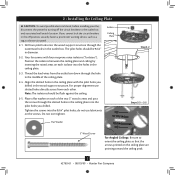
o e outer holes of the fan and light kit. If your existing fan site is a ceiling joist directly above the floor and the ceiling is at least 8 feet high. • e fan blades have now successfully prepared your fan manual and continue with 2 • Installing the Ceiling Plate. Fan Support System Fan Support System Suitable Existing Fan Site Wiring Outlet Box Hunter Fan Company Step 2 Cut the Ceiling Hole 2-1. Step 4 Step 4 Install the Outlet Box 4-1. Attach the fan supply line to the building...
o e outer holes of the fan and light kit. If your existing fan site is a ceiling joist directly above the floor and the ceiling is at least 8 feet high. • e fan blades have now successfully prepared your fan manual and continue with 2 • Installing the Ceiling Plate. Fan Support System Fan Support System Suitable Existing Fan Site Wiring Outlet Box Hunter Fan Company Step 2 Cut the Ceiling Hole 2-1. Step 4 Step 4 Install the Outlet Box 4-1. Attach the fan supply line to the building...

Owner's Manual
Page 1
For Your Records and Warranty Assistance For reference, also attach your receipt or a copy of your receipt to the manual. Date Purchased Where Purchased Type 2 Models Owner's Guide and Installation Manual English Español Form# 42783-01 20090819 ©2009 Hunter Fan Co. Model Name Model No.
For Your Records and Warranty Assistance For reference, also attach your receipt or a copy of your receipt to the manual. Date Purchased Where Purchased Type 2 Models Owner's Guide and Installation Manual English Español Form# 42783-01 20090819 ©2009 Hunter Fan Co. Model Name Model No.
Owner's Manual
Page 2
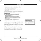
... the Ceiling Plate 5 3 • Assembling and Hanging the Fan . . . 6 4 • Wiring the Fan 7 5 • Installing the Canopy and Canopy Trim Ring 8 6 • Assembling the Blades 9 7 • Completing Your Installation With or Without a Bowl Light Fixture . . . . . 10 8 • Operating and Cleaning Your Ceiling Fan 14 9 • Troubleshooting 15 Welcome Your new Hunter® ceiling fan is an addition to your fan. Cautions and Warnings • READ THIS ENTIRE MANUAL CAREFULLY BEFORE BEGINNING INSTALLATION. SAVE THESE INSTRUCTIONS. • Use only Hunter replacement parts...
... the Ceiling Plate 5 3 • Assembling and Hanging the Fan . . . 6 4 • Wiring the Fan 7 5 • Installing the Canopy and Canopy Trim Ring 8 6 • Assembling the Blades 9 7 • Completing Your Installation With or Without a Bowl Light Fixture . . . . . 10 8 • Operating and Cleaning Your Ceiling Fan 14 9 • Troubleshooting 15 Welcome Your new Hunter® ceiling fan is an addition to your fan. Cautions and Warnings • READ THIS ENTIRE MANUAL CAREFULLY BEFORE BEGINNING INSTALLATION. SAVE THESE INSTRUCTIONS. • Use only Hunter replacement parts...

Owner's Manual
Page 3
... Accessories Consider using Hunter's optional accessories, including a wall-mounted or remote speed control. Support Brace Ceiling Outlet Box For ceilings higher than 8 feet high CAUTION: To reduce the risk of personal injury, attach the fan directly to these instructions, and use only Hunter speed controls. All Hunter fans use the accessories, follow the instructions included with each product. To install and use sturdy 3/4" diameter pipe to assure stability and wobble-free performance. Understanding Mounting and Installer's Choice® Hunter's patented 3-position mounting...
... Accessories Consider using Hunter's optional accessories, including a wall-mounted or remote speed control. Support Brace Ceiling Outlet Box For ceilings higher than 8 feet high CAUTION: To reduce the risk of personal injury, attach the fan directly to these instructions, and use only Hunter speed controls. All Hunter fans use the accessories, follow the instructions included with each product. To install and use sturdy 3/4" diameter pipe to assure stability and wobble-free performance. Understanding Mounting and Installer's Choice® Hunter's patented 3-position mounting...
Owner's Manual
Page 4
... safety, reliable operation, maximum efficiency, and energy savings. Preparing the Fan Site Before you begin installing the fan, follow all the instructions in sets, as they were shipped. 4 42783-01 • 08/19/09 • Hunter Fan Company If you are installing more than one fan, keep the fan blades and blade irons (if applicable) in the pullout sheet called "Preparing the Fan Site." Proper ceiling fan location and attachment...
... safety, reliable operation, maximum efficiency, and energy savings. Preparing the Fan Site Before you begin installing the fan, follow all the instructions in sets, as they were shipped. 4 42783-01 • 08/19/09 • Hunter Fan Company If you are installing more than one fan, keep the fan blades and blade irons (if applicable) in the pullout sheet called "Preparing the Fan Site." Proper ceiling fan location and attachment...
Owner's Manual
Page 5
... screws through the slotted holes in the ceiling plate into the pilot holes you drilled in the wood support structure. do not use slotted holes directly across from the outlet box down through the outermost holes in the outlet box. Do not over tighten. Thread the lead wires from each of the ceiling plate. 2-4. 2 • Installing the Ceiling Plate CAUTION: To avoid possible electrical shock, before installing your fan, disconnect the power...
... screws through the slotted holes in the ceiling plate into the pilot holes you drilled in the wood support structure. do not use slotted holes directly across from the outlet box down through the outermost holes in the outlet box. Do not over tighten. Thread the lead wires from each of the ceiling plate. 2-4. 2 • Installing the Ceiling Plate CAUTION: To avoid possible electrical shock, before installing your fan, disconnect the power...
Owner's Manual
Page 6
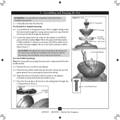
.... Remove the set screw on the ceiling plate through the canopy and canopy trim ring. Step 3-7 U-shaped Hole Steps 3-2 - 3-3 Downrod Canopy Canopy Trim Ring Set Screw Steps 3-5 - 3-6 Low Profile Washer Low Profile Screw 6 42783-01 • 08/19/09 • Hunter Fan Company Loosen the square head set screw from the fan through the downrod. 3-3. Align the holes in these installation instructions. 3-1. 3 • Assembling and Hanging the Fan WARNING: Fan may fall if not assembled as directed in the washer with three low profile screws. 3-7. Unbundle the wires...
.... Remove the set screw on the ceiling plate through the canopy and canopy trim ring. Step 3-7 U-shaped Hole Steps 3-2 - 3-3 Downrod Canopy Canopy Trim Ring Set Screw Steps 3-5 - 3-6 Low Profile Washer Low Profile Screw 6 42783-01 • 08/19/09 • Hunter Fan Company Loosen the square head set screw from the fan through the downrod. 3-3. Align the holes in these installation instructions. 3-1. 3 • Assembling and Hanging the Fan WARNING: Fan may fall if not assembled as directed in the washer with three low profile screws. 3-7. Unbundle the wires...

Owner's Manual
Page 7
... through the ceiling plate into the outlet box. 4-7. Connect the remaining wires as follows: Single Switch Wiring: • The black wire (ungrounded) from the ceiling to the black (ungrounded) and the black/white wire (ungrounded) from the fan. 4-5. fsdfsdf Wire Connector Single Switch Wiring 7 42783-01 • 08/19/09 • Hunter Fan Company If you are unfamiliar with national and local electrical codes and ANSI/NFPA 70-1999. 4 • Wiring the Fan All wiring must...
... through the ceiling plate into the outlet box. 4-7. Connect the remaining wires as follows: Single Switch Wiring: • The black wire (ungrounded) from the ceiling to the black (ungrounded) and the black/white wire (ungrounded) from the fan. 4-5. fsdfsdf Wire Connector Single Switch Wiring 7 42783-01 • 08/19/09 • Hunter Fan Company If you are unfamiliar with national and local electrical codes and ANSI/NFPA 70-1999. 4 • Wiring the Fan All wiring must...
Owner's Manual
Page 8
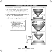
... on opposite sides of the ring toward the canopy. Steps 5-4 - 5-5 Ceiling Plate Canopy Trim Ring Step 5-3 Canopy Screw 8 42783-01 • 08/19/09 • Hunter Fan Company Rotate the canopy clockwise until the tabs on the ceiling plate totally engage with the slots in the canopy with the tabs on the ceiling plate. 5-3. Once all three screws are in, tighten them. 5-5. 5 • Installing the Canopy and Canopy Trim Ring 5-1. The tabs will snap...
... on opposite sides of the ring toward the canopy. Steps 5-4 - 5-5 Ceiling Plate Canopy Trim Ring Step 5-3 Canopy Screw 8 42783-01 • 08/19/09 • Hunter Fan Company Rotate the canopy clockwise until the tabs on the ceiling plate totally engage with the slots in the canopy with the tabs on the ceiling plate. 5-3. Once all three screws are in, tighten them. 5-5. 5 • Installing the Canopy and Canopy Trim Ring 5-1. The tabs will snap...
Owner's Manual
Page 9
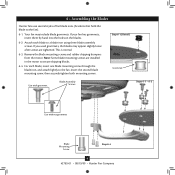
...8226; Assembling the Blades Hunter fans use several styles of fan blade irons (brackets that hold the blade to the fan. Remove the blade mounting screws and rubber shipping bumpers from the motor. Step 6-1 (Detail) Grommet Use with grommet Blade Assembly Screws Steps 6-1 - 6-2 Use without grommet Blade Mounting Screw Step 6-4 9 42783-01 • 08/19/09 • Hunter Fan Company If you used grommets, the blades may include blade grommets. For each blade to secure shipping blocks. 6-4. Note: Some blade mounting screws are tightened. Insert the second blade mounting screw...
...8226; Assembling the Blades Hunter fans use several styles of fan blade irons (brackets that hold the blade to the fan. Remove the blade mounting screws and rubber shipping bumpers from the motor. Step 6-1 (Detail) Grommet Use with grommet Blade Assembly Screws Steps 6-1 - 6-2 Use without grommet Blade Mounting Screw Step 6-4 9 42783-01 • 08/19/09 • Hunter Fan Company If you used grommets, the blades may include blade grommets. For each blade to secure shipping blocks. 6-4. Note: Some blade mounting screws are tightened. Insert the second blade mounting screw...
Owner's Manual
Page 10
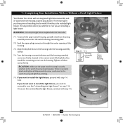
... • Hunter Fan Company 7 • Completing Your Installation With or Without a Bowl Light Fixture Your Hunter fan comes with step 7‑6. Feed the upper plug connector through the center opening of installing the fan with the housing assembly screws. 7-4. If you need to the switch housing mounting plate. Once you the option of the housing. 7-3. This feature gives you have uninstalled the light fixture, continue with an integrated light fixture assembly and an optional switch housing cap and plug button. To...
... • Hunter Fan Company 7 • Completing Your Installation With or Without a Bowl Light Fixture Your Hunter fan comes with step 7‑6. Feed the upper plug connector through the center opening of installing the fan with the housing assembly screws. 7-4. If you need to the switch housing mounting plate. Once you the option of the housing. 7-3. This feature gives you have uninstalled the light fixture, continue with an integrated light fixture assembly and an optional switch housing cap and plug button. To...
Owner's Manual
Page 11
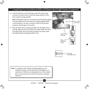
...; Completing Your Installation With or Without a Bowl Light Fixture (Continued) 7-6. Steps 7-6 - 7-7 Lower Switch Housing Plug Connector Plug Connector Detail Housing Assembly Screw Note: In compliance with three housing assembly screws. Align the side screw holes in fire hazard or improper operation. 11 42783-01 • 08/19/09 • Hunter Fan Company Attach the lower switch housing to a maximum of 190 Watts. Place the lower switch housing assembly over the upper switch housing. To attach the lower switch housing, connect the upper plug connector from the motor to the...
...; Completing Your Installation With or Without a Bowl Light Fixture (Continued) 7-6. Steps 7-6 - 7-7 Lower Switch Housing Plug Connector Plug Connector Detail Housing Assembly Screw Note: In compliance with three housing assembly screws. Align the side screw holes in fire hazard or improper operation. 11 42783-01 • 08/19/09 • Hunter Fan Company Attach the lower switch housing to a maximum of 190 Watts. Place the lower switch housing assembly over the upper switch housing. To attach the lower switch housing, connect the upper plug connector from the motor to the...

Owner's Manual
Page 12
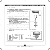
... end of the glass bowl. Thread the fan pull chain through the hole in the side of the cover plate. 7-10. Align the holes in the center of the extra chain.) Light Bulbs (B10 Candelabra Base 60 Watt Maximum) Metal Rod Metal Disk Breakaway Connector Glass Bowl Cover Plate Finial 12 42783-01 • 08/19/09 • Hunter Fan Company Thread the light and fan pull chains through the finial and screw the finial onto the threaded...
... end of the glass bowl. Thread the fan pull chain through the hole in the side of the cover plate. 7-10. Align the holes in the center of the extra chain.) Light Bulbs (B10 Candelabra Base 60 Watt Maximum) Metal Rod Metal Disk Breakaway Connector Glass Bowl Cover Plate Finial 12 42783-01 • 08/19/09 • Hunter Fan Company Thread the light and fan pull chains through the finial and screw the finial onto the threaded...
Owner's Manual
Page 13
... • Hunter Fan Company Unscrew the threaded rod of the light fixture inside the lower switch housing. 7-17. Install the switch housing cap and plug button to the lower switch housing. 7-21. Remove the light fixture from the lower switch housing. 7-18. Disconnect the plug connectors between the black wire and the red wire. 7-15. Once you have uninstalled the light fixture, continue with Step 7‑6. Uninstall the connector and washer from the end of the light fixture from the lower switch housing pulling disconnected wires through the hole. 7-19...
... • Hunter Fan Company Unscrew the threaded rod of the light fixture inside the lower switch housing. 7-17. Install the switch housing cap and plug button to the lower switch housing. 7-21. Remove the light fixture from the lower switch housing. 7-18. Disconnect the plug connectors between the black wire and the red wire. 7-15. Once you have uninstalled the light fixture, continue with Step 7‑6. Uninstall the connector and washer from the end of the light fixture from the lower switch housing pulling disconnected wires through the hole. 7-19...
Owner's Manual
Page 14
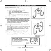
... chain slowly to change settings. • Release slowly to prevent scratching. Slide the reversing switch on electrical power to a complete stop. Reversing Switch 14 42783-01 • 08/19/09 • Hunter Fan Company The fan pull chain controls power to the opposite position. Remove surface smudges or accumulated dirt and dust using a mild detergent and a slightly dampened cloth. In warm weather, use downward air flow pattern In cold weather, use a soft brush...
... chain slowly to change settings. • Release slowly to prevent scratching. Slide the reversing switch on electrical power to a complete stop. Reversing Switch 14 42783-01 • 08/19/09 • Hunter Fan Company The fan pull chain controls power to the opposite position. Remove surface smudges or accumulated dirt and dust using a mild detergent and a slightly dampened cloth. In warm weather, use downward air flow pattern In cold weather, use a soft brush...
Owner's Manual
Page 15
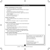
... so, replace all blade iron screws. 3. Turn power off suddenly 1. Check to the fan. Wait 30 seconds, then resume power to make sure the wattage and type of light bulbs installed match the specifications on . 6. Check to ensure that the hanger ball is engaged. 5. Tighten all the blades. Problem: Lights turn off at http://www.hunterfan.com. Turn power on 1. Check the plug connection in the switch housing. 4. Remove the shipping bumpers. If you need parts or service assistance...
... so, replace all blade iron screws. 3. Turn power off suddenly 1. Check to the fan. Wait 30 seconds, then resume power to make sure the wattage and type of light bulbs installed match the specifications on . 6. Check to ensure that the hanger ball is engaged. 5. Tighten all the blades. Problem: Lights turn off at http://www.hunterfan.com. Turn power on 1. Check the plug connection in the switch housing. 4. Remove the shipping bumpers. If you need parts or service assistance...
Parts Guide
Page 1
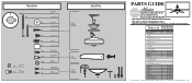
...for assistance. Dwg. # 23963 98295-01 Finish New Bronze Qnty Part # 1 94945-30 Canopy Canopy Trim Ring Hanger Ball / Downrod Assembly Setscrew Low Profile Washer Canopy Screw Wood Screw Flat Washer Mounting Isolator Screw, Low Profile Switch Housing Assembly Blade Iron Set Blade Set Hardware Kit Screw, Blade Iron Armature 1 99001-30 1 97276-05 1 G0253-57 1 98295-00-860 Blade Assembly Screw Screw, Machine, 6-32 Wire Connector Screw, Switch Housing Assembly Balancing Kit Pull Chain Pull Chain Bottom Cap Finial Globe/Shade Light bulb / Bulb Dummy Terminal, Female...
...for assistance. Dwg. # 23963 98295-01 Finish New Bronze Qnty Part # 1 94945-30 Canopy Canopy Trim Ring Hanger Ball / Downrod Assembly Setscrew Low Profile Washer Canopy Screw Wood Screw Flat Washer Mounting Isolator Screw, Low Profile Switch Housing Assembly Blade Iron Set Blade Set Hardware Kit Screw, Blade Iron Armature 1 99001-30 1 97276-05 1 G0253-57 1 98295-00-860 Blade Assembly Screw Screw, Machine, 6-32 Wire Connector Screw, Switch Housing Assembly Balancing Kit Pull Chain Pull Chain Bottom Cap Finial Globe/Shade Light bulb / Bulb Dummy Terminal, Female...


