
Installation Guide
Page 1
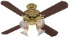
... o e electrical cable is secured to the joist or support brace by the support brace manufacturer). Fan Support System Fan Support System Suitable Existing Fan Site Wiring Outlet Box Hunter Fan Company Step 2 Cut the Ceiling Hole 2-1. Position it to allow you to recess the bottom of the...approved octagonal 4" x 1-1/2" outlet box (or as follows: 3-1. For instructions to install your ceiling fan, go to your new Hunter fan. Cut a 4" diameter hole through the inner holes of the fan. If the joist is there, determine if it will hold the outlet box and the full weight ...
... o e electrical cable is secured to the joist or support brace by the support brace manufacturer). Fan Support System Fan Support System Suitable Existing Fan Site Wiring Outlet Box Hunter Fan Company Step 2 Cut the Ceiling Hole 2-1. Position it to allow you to recess the bottom of the...approved octagonal 4" x 1-1/2" outlet box (or as follows: 3-1. For instructions to install your ceiling fan, go to your new Hunter fan. Cut a 4" diameter hole through the inner holes of the fan. If the joist is there, determine if it will hold the outlet box and the full weight ...
Owner's Manual
Page 1
...in Step 3 below. If you are unfamiliar with wiring, you should extend at main panel before beginning installation. 2. Use Hunter Controls only. 2. B. Unpack the fan carefully to avoid any shipping damage to the components. All wiring must be mounted at the fuse panel when inspecting or ... codes. Step 2: Inspection of personal injury, do not use no larger than one of Outlet Box and Rough-In Wiring CAUTION: Your Hunter ceiling fan with national and local electrical codes. If more than the minor diameter of parts. Check contents to 35 lbs. C. C. Orient the ...
...in Step 3 below. If you are unfamiliar with wiring, you should extend at main panel before beginning installation. 2. Use Hunter Controls only. 2. B. Unpack the fan carefully to avoid any shipping damage to the components. All wiring must be mounted at the fuse panel when inspecting or ... codes. Step 2: Inspection of personal injury, do not use no larger than one of Outlet Box and Rough-In Wiring CAUTION: Your Hunter ceiling fan with national and local electrical codes. If more than the minor diameter of parts. Check contents to 35 lbs. C. C. Orient the ...
Owner's Manual
Page 2
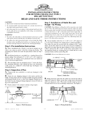
... Profile Version B. Secure the canopy to the top of the fan using the (3) #8-32 x 3/4" long screws with the vertical flange of the canopy after the fan is facing down position. FORM NO. 41184-01 10/05 -2- ©2005 HUNTER FAN CO. Read Steps 5-1 and 5-2 to the top of the... the top of the canopy. C. NOTE: Assembly Methods for Installer's Choice Hanging System Your new Hunter fan can be attached to decide which supports the outlet box. Place the canopy assembly washer inside of the fan. Use (2) #10 wood screws 3" long and (2) flat washers for mounting screws 9/64" diameter...
... Profile Version B. Secure the canopy to the top of the fan using the (3) #8-32 x 3/4" long screws with the vertical flange of the canopy after the fan is facing down position. FORM NO. 41184-01 10/05 -2- ©2005 HUNTER FAN CO. Read Steps 5-1 and 5-2 to the top of the... the top of the canopy. C. NOTE: Assembly Methods for Installer's Choice Hanging System Your new Hunter fan can be attached to decide which supports the outlet box. Place the canopy assembly washer inside of the fan. Use (2) #10 wood screws 3" long and (2) flat washers for mounting screws 9/64" diameter...
Owner's Manual
Page 3
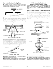
...supply lead to the adaptor. The canopy has (3) suspen- The ceiling plate has (3) mating slots. GREEN GROUND WIRE CONNECTOR CANOPY CEILING PLATE HOOK FAN Figure 5B. See Figure 5C. Aligning Tab & Groove NOTE: When attaching the canopy to the black motor lead and the black with the ... the ceiling plate using approved connectors. CANOPY CEILING PLATE FLANGE SLOT Figure 6 Figure 6A FORM NO. 41184-01 10/05 -3- ©2005 HUNTER FAN CO. See Figure 5D. sion flanges located on top. See Figure 5B. Connect the ground wire to scratch the canopy finish, hang the...
...supply lead to the adaptor. The canopy has (3) suspen- The ceiling plate has (3) mating slots. GREEN GROUND WIRE CONNECTOR CANOPY CEILING PLATE HOOK FAN Figure 5B. See Figure 5C. Aligning Tab & Groove NOTE: When attaching the canopy to the black motor lead and the black with the ... the ceiling plate using approved connectors. CANOPY CEILING PLATE FLANGE SLOT Figure 6 Figure 6A FORM NO. 41184-01 10/05 -3- ©2005 HUNTER FAN CO. See Figure 5D. sion flanges located on top. See Figure 5B. Connect the ground wire to scratch the canopy finish, hang the...

Owner's Manual
Page 4
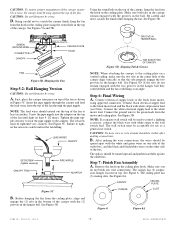
... SWITCH HOUSING BLADE BREAKAWAY CONNECTOR REVERSING SWITCH Figure 8 GROMMET Figure 8A Figure 10 First connect the upper and lower plug connectors. Lift the fan and position the (3) flanges in the canopy into the holes in blade bracket. Insert a mounting screw (provided) in hole in the ceiling...blades may use a tool, make certain the (2) tabs in the canopy. FORM NO. 41184-01 10/05 -4- ©2005 HUNTER FAN CO. Should the fan wobble in the fan falling. See Figure 5D. Next assemble the blade to the ceiling plate. A blade balancing kit has been provided with the (3)...
... SWITCH HOUSING BLADE BREAKAWAY CONNECTOR REVERSING SWITCH Figure 8 GROMMET Figure 8A Figure 10 First connect the upper and lower plug connectors. Lift the fan and position the (3) flanges in the canopy into the holes in blade bracket. Insert a mounting screw (provided) in hole in the ceiling...blades may use a tool, make certain the (2) tabs in the canopy. FORM NO. 41184-01 10/05 -4- ©2005 HUNTER FAN CO. Should the fan wobble in the fan falling. See Figure 5D. Next assemble the blade to the ceiling plate. A blade balancing kit has been provided with the (3)...
Owner's Manual
Page 5
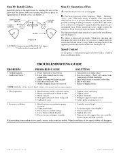
... screws. Noisy operation. 1. Blade brackets loosely screwed to blade bracket. 3. Light globe noisy. 1. Replace all screws. 5. Unbalanced blades. 3. Fan not secure on or replace fuse. 2. FORM NO. 41184-01 10/05 -5- ©2005 HUNTER FAN CO. See Figure 10. Slide reversing switch to operate. TROUBLESHOOTING GUIDE PROBLEM PROBABLE CAUSE 1. Tighten screws until snug...
... screws. Noisy operation. 1. Blade brackets loosely screwed to blade bracket. 3. Light globe noisy. 1. Replace all screws. 5. Unbalanced blades. 3. Fan not secure on or replace fuse. 2. FORM NO. 41184-01 10/05 -5- ©2005 HUNTER FAN CO. See Figure 10. Slide reversing switch to operate. TROUBLESHOOTING GUIDE PROBLEM PROBABLE CAUSE 1. Tighten screws until snug...

Parts Guide
Page 1
..., Canopy Trim Ring Globe/Shade Light bulb / Bulb Balancing Kit Model # Asm. REFER TO THE INSTALLATION MANUAL FOR FULL ASSEMBLY INSTRUCTIONS. Dwg. # Finish Qnty 23710 92582-01 Burnished Brass Part # 1 84102-01 1 92581-01 1 84095-01 1 74228-03 1 74017-09 1 74002-75 9 63755-05 1 83905/3... 3 64555-01 12 03435-03 1 92582-00-860 4 07649-01 4 77646-04 1 07570-01 Hunter Fan Company • 7130 Goodlett Farms Pkwy #400 • Memphis, TN 38016 • www.hunterfan.com • 98000-01-472 06-11-2009 • ©...
..., Canopy Trim Ring Globe/Shade Light bulb / Bulb Balancing Kit Model # Asm. REFER TO THE INSTALLATION MANUAL FOR FULL ASSEMBLY INSTRUCTIONS. Dwg. # Finish Qnty 23710 92582-01 Burnished Brass Part # 1 84102-01 1 92581-01 1 84095-01 1 74228-03 1 74017-09 1 74002-75 9 63755-05 1 83905/3... 3 64555-01 12 03435-03 1 92582-00-860 4 07649-01 4 77646-04 1 07570-01 Hunter Fan Company • 7130 Goodlett Farms Pkwy #400 • Memphis, TN 38016 • www.hunterfan.com • 98000-01-472 06-11-2009 • ©...


