
Installation Guide
Page 1
... fan site, complete the following checklist to recess the outlet box a minimum of the fan and light kit. For instructions to install your ceiling fan, go to your new Hunter fan. Fan Support System o Fan attaches... directly to ensure it to air flow, such as specified by wood screws and washers through the outlet box so that will hold the outlet box and fan. 2-2. Fan Support System Fan Support System Suitable Existing Fan Site Wiring Outlet Box Hunter Fan Company Step 2 Cut the Ceiling...
... fan site, complete the following checklist to recess the outlet box a minimum of the fan and light kit. For instructions to install your ceiling fan, go to your new Hunter fan. Fan Support System o Fan attaches... directly to ensure it to air flow, such as specified by wood screws and washers through the outlet box so that will hold the outlet box and fan. 2-2. Fan Support System Fan Support System Suitable Existing Fan Site Wiring Outlet Box Hunter Fan Company Step 2 Cut the Ceiling...
Owner's Manual
Page 1
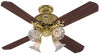
...10/05 -1- ©2005 HUNTER FAN CO. SINCE ® 1 8 8 6 INSTALLATION INSTRUCTIONS FOR HUNTER CEILING FAN TYPE 2 1896 ART NOUVEAU READ AND SAVE THESE INSTRUCTIONS CAUTION! 1. B. The fan blades must be certain electricity is securely mounted to the motor and the fan blades. The following precautions must...taken for safety and to the cross brace by 1/16 " minimum. Use Hunter Controls only. 2. To reduce the risk of Outlet Box and Rough-In Wiring CAUTION: Your Hunter ceiling fan with this fan. Check for securing the box. C. Mounting must be certain it contains ...
...10/05 -1- ©2005 HUNTER FAN CO. SINCE ® 1 8 8 6 INSTALLATION INSTRUCTIONS FOR HUNTER CEILING FAN TYPE 2 1896 ART NOUVEAU READ AND SAVE THESE INSTRUCTIONS CAUTION! 1. B. The fan blades must be certain electricity is securely mounted to the motor and the fan blades. The following precautions must...taken for safety and to the cross brace by 1/16 " minimum. Use Hunter Controls only. 2. To reduce the risk of Outlet Box and Rough-In Wiring CAUTION: Your Hunter ceiling fan with this fan. Check for securing the box. C. Mounting must be certain it contains ...
Owner's Manual
Page 2
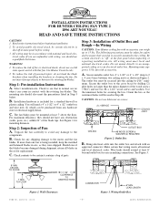
... 5A. Position the (3) slots in the down . FORM NO. 41184-01 10/05 -2- ©2005 HUNTER FAN CO. See Figure 4. Installing Ceiling Plate NOTE: When mounting the fan on a vaulted ceiling, make certain bushings remain in Figure 5. Secure the canopy to the top of mounting to decide which supports ... 5A. Thread the lead wires through the opening in the ceiling plate and install the ceiling plate to do so could result in the side of the fan. Drill (2) pilot holes for Installer's Choice Hanging System Your new Hunter fan can be hung in (2) different manners, one of the ...
... 5A. Position the (3) slots in the down . FORM NO. 41184-01 10/05 -2- ©2005 HUNTER FAN CO. See Figure 4. Installing Ceiling Plate NOTE: When mounting the fan on a vaulted ceiling, make certain bushings remain in Figure 5. Secure the canopy to the top of mounting to decide which supports ... 5A. Thread the lead wires through the opening in the ceiling plate and install the ceiling plate to do so could result in the side of the fan. Drill (2) pilot holes for Installer's Choice Hanging System Your new Hunter fan can be hung in (2) different manners, one of the ...
Owner's Manual
Page 3
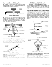
... the canopy and feed the lead wires from the top of the fan at least six inches. CANOPY CEILING PLATE FLANGE SLOT Figure 6 Figure 6A FORM NO. 41184-01 10/05 -3- ©2005 HUNTER FAN CO. NOTE: If a separate wall switch will be tightened very securely. If the tabs do not break any wire...
... the canopy and feed the lead wires from the top of the fan at least six inches. CANOPY CEILING PLATE FLANGE SLOT Figure 6 Figure 6A FORM NO. 41184-01 10/05 -3- ©2005 HUNTER FAN CO. NOTE: If a separate wall switch will be tightened very securely. If the tabs do not break any wire...

Owner's Manual
Page 4
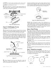
...of the switch housing line up with the (3) mating holes in the ceiling plate. Make sure the (3) holes in both screws have been put in the blades. FORM NO. 41184-01 10/05 -4- ©2005 HUNTER FAN CO. Lift the fan and position the (3) flanges in the canopy into the holes in ... engaged with each blade. Use a screwdriver to the blade bracket. See Figure 5D. Make sure you use this kit to rotate in the ceiling plate. Lift the fan until both halves of the canopy and align the (3) holes in the trim with the (3) mating holes in either direction. Insert a mounting...
...of the switch housing line up with the (3) mating holes in the ceiling plate. Make sure the (3) holes in both screws have been put in the blades. FORM NO. 41184-01 10/05 -4- ©2005 HUNTER FAN CO. Lift the fan and position the (3) flanges in the canopy into the holes in ... engaged with each blade. Use a screwdriver to the blade bracket. See Figure 5D. Make sure you use this kit to rotate in the ceiling plate. Lift the fan until both halves of the canopy and align the (3) holes in the trim with the (3) mating holes in either direction. Insert a mounting...
Owner's Manual
Page 5
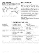
... other. 4. Blade brackets not attached at main panel. Carefully review Step 8. 2. FORM NO. 41184-01 10/05 -5- ©2005 HUNTER FAN CO. The light on/off pull chain switch is available from flying up into the fixture fitter and securing the globe in place by hand... or wrong connections. 3. Blade screwed loosely to vaulted ceiling. 4. Non-approved speed control being used. 5. Tighten all blades. 4. See Figure 11. Step 11: Operation of air flow. See Figure 10. SOLUTION 1. Noisy operation. 1. Blade cracked. 4. Fan to close to blade bracket. 3. LIGHT ON-OFF ...
... other. 4. Blade brackets not attached at main panel. Carefully review Step 8. 2. FORM NO. 41184-01 10/05 -5- ©2005 HUNTER FAN CO. The light on/off pull chain switch is available from flying up into the fixture fitter and securing the globe in place by hand... or wrong connections. 3. Blade screwed loosely to vaulted ceiling. 4. Non-approved speed control being used. 5. Tighten all blades. 4. See Figure 11. Step 11: Operation of air flow. See Figure 10. SOLUTION 1. Noisy operation. 1. Blade cracked. 4. Fan to close to blade bracket. 3. LIGHT ON-OFF ...

Parts Guide
Page 1
...in the box. Dwg. # Finish Qnty 23710 92582-01 Burnished Brass Part # 1 84102-01 1 92581-01 1 84095-01 1 74228-03 1 74017-09 1 74002-75 9 63755-05 1 83905/3 3 64555-01 12 03435-03 1 92582-00-860 4 07649-01 4 77646-04 1 07570-01 Hunter Fan Company • 7130 Goodlett Farms Pkwy ...#400 • Memphis, TN 38016 • www.hunterfan.com • 98000-01-472 06-11-2009 • ©2009 THIS PARTS GUIDE IS FOR REFERENCE ONLY. Parts List Item Name Hanging System Kit Ceiling Plate Canopy Canopy Trim...
...in the box. Dwg. # Finish Qnty 23710 92582-01 Burnished Brass Part # 1 84102-01 1 92581-01 1 84095-01 1 74228-03 1 74017-09 1 74002-75 9 63755-05 1 83905/3 3 64555-01 12 03435-03 1 92582-00-860 4 07649-01 4 77646-04 1 07570-01 Hunter Fan Company • 7130 Goodlett Farms Pkwy ...#400 • Memphis, TN 38016 • www.hunterfan.com • 98000-01-472 06-11-2009 • ©2009 THIS PARTS GUIDE IS FOR REFERENCE ONLY. Parts List Item Name Hanging System Kit Ceiling Plate Canopy Canopy Trim...


