
Installation Guide
Page 1
...-approved octagonal 4" x 1-1/2" outlet box (or as specified by the support brace manufacturer). o Fan support system will hold full weight of the ceiling. o e outer holes of the fan. Wiring o e electrical cable is a ceiling joist directly above the floor and the ceiling is at any hardware store or electrical supply house. 4-2. Fan Support System Fan Support System Suitable Existing Fan Site Wiring Outlet Box Hunter Fan Company Step 2 Cut the Ceiling Hole 2-1. Steps 2 - 3 Step 3 Install a Support Brace, If Necessary Determine...
...-approved octagonal 4" x 1-1/2" outlet box (or as specified by the support brace manufacturer). o Fan support system will hold full weight of the ceiling. o e outer holes of the fan. Wiring o e electrical cable is a ceiling joist directly above the floor and the ceiling is at any hardware store or electrical supply house. 4-2. Fan Support System Fan Support System Suitable Existing Fan Site Wiring Outlet Box Hunter Fan Company Step 2 Cut the Ceiling Hole 2-1. Steps 2 - 3 Step 3 Install a Support Brace, If Necessary Determine...

Owner's Manual
Page 1
For Your Records and Warranty Assistance Model Name Catalog/Model No Serial No Date Purchased Where Purchased For reference also attach your receipt or a copy of your receipt to the manual. 42701-01 • 01/25/06
For Your Records and Warranty Assistance Model Name Catalog/Model No Serial No Date Purchased Where Purchased For reference also attach your receipt or a copy of your receipt to the manual. 42701-01 • 01/25/06

Owner's Manual
Page 2
...the fan directly to the support structure of the building according to these instructions, and use only the hardware supplied. • To avoid possible electrical shock, before beginning installation. Welcome 2 Table of Contents 1 • Getting Ready 4 2 • Installing the Ceiling Plate 5 3 • Assembling and Hanging the Fan..........6 4 • Wiring the Fan 7 5 • Installing the Canopy 8 6 • Assembling the Blades 9 7 • Operating and Cleaning Your Ceiling Fan 10 8 • Troubleshooting 11 © 2006 Hunter Fan Company Hunter Fan Company Your new Hunter...
...the fan directly to the support structure of the building according to these instructions, and use only the hardware supplied. • To avoid possible electrical shock, before beginning installation. Welcome 2 Table of Contents 1 • Getting Ready 4 2 • Installing the Ceiling Plate 5 3 • Assembling and Hanging the Fan..........6 4 • Wiring the Fan 7 5 • Installing the Canopy 8 6 • Assembling the Blades 9 7 • Operating and Cleaning Your Ceiling Fan 10 8 • Troubleshooting 11 © 2006 Hunter Fan Company Hunter Fan Company Your new Hunter...
Owner's Manual
Page 3
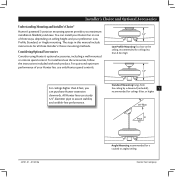
... of three ways, depending on ceiling height and your preference: Low Profile, Standard, or Angle mounting. e steps in one of your Hunter fan in this manual include instructions for a vaulted or angled ceiling Hunter Fan Company Low Profile Mounting fits close to assure stability and wobble-free performance. Installer's Choice and Optional Accessories Understanding Mounting and Installer's Choice® Hunter's patented 3-position mounting system provides you can install your Hunter fan, use only Hunter speed controls. You can purchase Hunter extension downrods.
... of three ways, depending on ceiling height and your preference: Low Profile, Standard, or Angle mounting. e steps in one of your Hunter fan in this manual include instructions for a vaulted or angled ceiling Hunter Fan Company Low Profile Mounting fits close to assure stability and wobble-free performance. Installer's Choice and Optional Accessories Understanding Mounting and Installer's Choice® Hunter's patented 3-position mounting system provides you can install your Hunter fan, use only Hunter speed controls. You can purchase Hunter extension downrods.

Owner's Manual
Page 4
... direct you begin installing the fan, follow all the instructions in the pullout sheet called "Preparing the Fan Site." Refer to the motor or fan blades. Hunter Fan Company 42701-01 • 01/25/06 If you need the following : • Locate the ceiling joist or other suitable support in sets, as they were shipped. If any shipping damage to the included Parts Guide. Gathering the Tools You will need help installing the fan...
... direct you begin installing the fan, follow all the instructions in the pullout sheet called "Preparing the Fan Site." Refer to the motor or fan blades. Hunter Fan Company 42701-01 • 01/25/06 If you need the following : • Locate the ceiling joist or other suitable support in sets, as they were shipped. If any shipping damage to the included Parts Guide. Gathering the Tools You will need help installing the fan...

Owner's Manual
Page 5
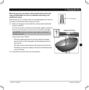
... hanger bracket. Drill two pilot holes into the 9/64" pilot holes; Use a 3" wood screw to the outlet box and associated wall switch location. do not use slotted holes directly across from the outlet box down through the outermost holes in the ceiling plate with the slots and holes on each other. 2-3. Align the slotted holes in the outlet box. e pilot holes should be 9/64" in the wood support structure. Place a flat washer...
... hanger bracket. Drill two pilot holes into the 9/64" pilot holes; Use a 3" wood screw to the outlet box and associated wall switch location. do not use slotted holes directly across from the outlet box down through the outermost holes in the ceiling plate with the slots and holes on each other. 2-3. Align the slotted holes in the outlet box. e pilot holes should be 9/64" in the wood support structure. Place a flat washer...
Owner's Manual
Page 6
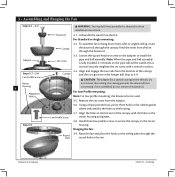
... used. 3-5. Remove the set screw with the holes in these installation instructions. Using a sharp pointed tool, pierce three holes in the rubber gasket where indicated by the holes in the hanger ball. Install three low profile screws to secure the canopy to 3-9. Set Screw 3-3. Align and engage the two tabs from the fan through the canopy. the coating prevents the downrod from a flat or angled ceiling, insert Canopy the downrod through the downrod. Once assembled, do not remove...
... used. 3-5. Remove the set screw with the holes in these installation instructions. Using a sharp pointed tool, pierce three holes in the rubber gasket where indicated by the holes in the hanger ball. Install three low profile screws to secure the canopy to 3-9. Set Screw 3-3. Align and engage the two tabs from the fan through the canopy. the coating prevents the downrod from a flat or angled ceiling, insert Canopy the downrod through the downrod. Once assembled, do not remove...
Owner's Manual
Page 7
... ceiling plate and the green ground wire from the fan • e white wire from the ceiling to the white wire from the fan • e black wire from the fan 4-2. If you are unfamiliar with national and local electrical codes and ANSI/NFPA 70. Push all wires and wire nuts into the outlet box. 4 • Wiring the Fan Wire Nut Single Switch Wiring 7 42701-01 • 01/25/06 Hunter Fan Company All wiring...
... ceiling plate and the green ground wire from the fan • e white wire from the ceiling to the white wire from the fan • e black wire from the fan 4-2. If you are unfamiliar with national and local electrical codes and ANSI/NFPA 70. Push all wires and wire nuts into the outlet box. 4 • Wiring the Fan Wire Nut Single Switch Wiring 7 42701-01 • 01/25/06 Hunter Fan Company All wiring...
Owner's Manual
Page 8
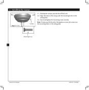
Note: If necessary, lift the side of the gasket to insert the screws into the mounting holes on the ceiling plate. 5-3. Insert and tighten the mounting screws securely. Holding the canopy, raise the fan off the hook. 5-2. Mounting Screw 8 Hunter Fan Company 42701-01 • 01/25/06 5 • Installing the Canopy Steps 5-1- 5-3 Canopy 5-1. Align the holes in the canopy with the mounting holes on the ceiling plate.
Note: If necessary, lift the side of the gasket to insert the screws into the mounting holes on the ceiling plate. 5-3. Insert and tighten the mounting screws securely. Holding the canopy, raise the fan off the hook. 5-2. Mounting Screw 8 Hunter Fan Company 42701-01 • 01/25/06 5 • Installing the Canopy Steps 5-1- 5-3 Canopy 5-1. Align the holes in the canopy with the mounting holes on the ceiling plate.

Owner's Manual
Page 9
... after screws are installed in the motor to the fan. Remove the blade mounting screws and rubber shipping bumpers from the motor. Use with grommet Blade Assembly Screws 6 • Assembling the Blades Step 6-1 (Detail) Grommet Steps 6-1 - 6-2 9 Use without grommet Blade Mounting Screw 42701-01 • 01/25/06 Step 6-4 Hunter Fan Company Attach each blade, insert one blade mounting screw through the blade iron, and attach lightly to secure shipping blocks during shipment. 6-4. If your fan has grommets, insert them by hand into the holes on the blades. 6-2. If you used grommets...
... after screws are installed in the motor to the fan. Remove the blade mounting screws and rubber shipping bumpers from the motor. Use with grommet Blade Assembly Screws 6 • Assembling the Blades Step 6-1 (Detail) Grommet Steps 6-1 - 6-2 9 Use without grommet Blade Mounting Screw 42701-01 • 01/25/06 Step 6-4 Hunter Fan Company Attach each blade, insert one blade mounting screw through the blade iron, and attach lightly to secure shipping blocks during shipment. 6-4. If your fan has grommets, insert them by hand into the holes on the blades. 6-2. If you used grommets...

Owner's Manual
Page 10
... blades with a direct breeze. In cold weather, use an artistic agent, but never abrasive cleaning agents, as the fan finish. Turn on the fan to prevent scratching. Clean painted and high-gloss blades in warm weather to cool the room with a furniture polishing cloth. Slide the reversing switch on electrical power to a complete stop. Reversing Switch Hunter Fan Company 42701-01 • 01/25/06 Ceiling fans work best by blowing air downward (counterclockwise blade...
... blades with a direct breeze. In cold weather, use an artistic agent, but never abrasive cleaning agents, as the fan finish. Turn on the fan to prevent scratching. Clean painted and high-gloss blades in warm weather to cool the room with a furniture polishing cloth. Slide the reversing switch on electrical power to a complete stop. Reversing Switch Hunter Fan Company 42701-01 • 01/25/06 Ceiling fans work best by blowing air downward (counterclockwise blade...
Owner's Manual
Page 11
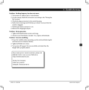
... balancing kit and instructions to the "Wiring the Fan" section. 3. If you need parts or service assistance, please call 888-830-1326 or visit us at our Web site at http://www.hunterfan.com. Turn power on . 6. Check the plug connection in the switch housing. 4. Tighten all the blades. Loosen canopy, check all connections according to balance the fan. 2. fan does not move. 1. Problem: Noisy operation. 1. Problem: Excessive wobbling. 1. Push motor reversing switch firmly...
... balancing kit and instructions to the "Wiring the Fan" section. 3. If you need parts or service assistance, please call 888-830-1326 or visit us at our Web site at http://www.hunterfan.com. Turn power on . 6. Check the plug connection in the switch housing. 4. Tighten all the blades. Loosen canopy, check all connections according to balance the fan. 2. fan does not move. 1. Problem: Noisy operation. 1. Problem: Excessive wobbling. 1. Push motor reversing switch firmly...
Parts Guide
Page 1
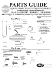
.... Call Technical Support at 901-248-2222. If parts are included in your records and warranty assistance. Date Purchased Where Purchased 7 Hanger Ball / Downrod Assembly Ceiling Plate 3 Canopy Motor Housing Assembly 74 Light Kit Adapter Missing / Broken Parts: Call 1-888-830-1326 Fan does not work: 1. For additional information on: Hunter Products Trouble Shooting Call 1-800-448-6837 www.hunterfan.com Blade Set 78 Pull Chain 76 Pull Chain Pendant 28 Switch Housing 29 Switch Housing Cover Hardware (Drawn to Scale) 5 Ceiling Plate Gasket Model Name Catalog No...
.... Call Technical Support at 901-248-2222. If parts are included in your records and warranty assistance. Date Purchased Where Purchased 7 Hanger Ball / Downrod Assembly Ceiling Plate 3 Canopy Motor Housing Assembly 74 Light Kit Adapter Missing / Broken Parts: Call 1-888-830-1326 Fan does not work: 1. For additional information on: Hunter Products Trouble Shooting Call 1-800-448-6837 www.hunterfan.com Blade Set 78 Pull Chain 76 Pull Chain Pendant 28 Switch Housing 29 Switch Housing Cover Hardware (Drawn to Scale) 5 Ceiling Plate Gasket Model Name Catalog No...

Parts Guide
Page 2
...01-607 1/12/06 Part List Item # Item Name * Hanging System Kit 2 Ceiling Plate 3 Canopy 5 Ceiling Plate Gasket 7 Hanger Ball / Downrod Assembly 8 Set Screw 62 Canopy Screw 64 Wood Screw 65 Wood Screw 68 Flat Washer 71 Isolator 100 Locking Screw 28 Switch Housing 29 Switch Housing Cover 40 Housing Cover Screw 44 Blade Iron Set 46 Blade Set 49 Light Kit Assembly (Not Shown) 74 Light Kit Adapter 76 Pull Chain Pendant 78 Pull Chain 150 Globe / Shade (Not Shown) * Hardware Kit 47 Screw, Blade Iron Armature 67 Blade Assembly Screw 70 Wire Nut 75...
...01-607 1/12/06 Part List Item # Item Name * Hanging System Kit 2 Ceiling Plate 3 Canopy 5 Ceiling Plate Gasket 7 Hanger Ball / Downrod Assembly 8 Set Screw 62 Canopy Screw 64 Wood Screw 65 Wood Screw 68 Flat Washer 71 Isolator 100 Locking Screw 28 Switch Housing 29 Switch Housing Cover 40 Housing Cover Screw 44 Blade Iron Set 46 Blade Set 49 Light Kit Assembly (Not Shown) 74 Light Kit Adapter 76 Pull Chain Pendant 78 Pull Chain 150 Globe / Shade (Not Shown) * Hardware Kit 47 Screw, Blade Iron Armature 67 Blade Assembly Screw 70 Wire Nut 75...


