
Installation Guide
Page 1
... or electrical supply house. 4-2. Drill pilot holes no obstructions to air flow, such as walls or posts, within 30 inches of the outlet box are turned off. For instructions to install your ceiling fan, go to your fan manual and continue with 2 • Installing the Ceiling Plate. CAUTION: All wiring must be in the off every item, prepare a new fan site as follows: 3-1. Position it will use the hole to install the support...
... or electrical supply house. 4-2. Drill pilot holes no obstructions to air flow, such as walls or posts, within 30 inches of the outlet box are turned off. For instructions to install your ceiling fan, go to your fan manual and continue with 2 • Installing the Ceiling Plate. CAUTION: All wiring must be in the off every item, prepare a new fan site as follows: 3-1. Position it will use the hole to install the support...

Owner's Manual
Page 1
For Your Records and Warranty Assistance For reference, also attach your receipt or a copy of your receipt to the manual. Date Purchased Where Purchased Type 2 Models Owner's Guide and Installation Manual English Español Form# 42600-01 20100622 ©2010 Hunter Fan Co. Model Name Model No.
For Your Records and Warranty Assistance For reference, also attach your receipt or a copy of your receipt to the manual. Date Purchased Where Purchased Type 2 Models Owner's Guide and Installation Manual English Español Form# 42600-01 20100622 ©2010 Hunter Fan Co. Model Name Model No.

Owner's Manual
Page 2
...; Hunter Fan Company This installation and operation manual gives you cannot lock the circuit breakers in the off the circuit breakers to the outlet box and associated wall switch location. Table Of Contents 1 • Getting Ready 6 2 • Installing the Ceiling Plate 7 3 • Assembling and Hanging the Fan . . . 8 4 • Wiring the Fan 9 5 • Installing the Canopy and Canopy Trim Ring 10 6 • Assembling the Blades 11 7 • Completing Your Installation With or Without a Bowl Light Fixture 12 8 • Operating and Cleaning Your Ceiling Fan...
...; Hunter Fan Company This installation and operation manual gives you cannot lock the circuit breakers in the off the circuit breakers to the outlet box and associated wall switch location. Table Of Contents 1 • Getting Ready 6 2 • Installing the Ceiling Plate 7 3 • Assembling and Hanging the Fan . . . 8 4 • Wiring the Fan 9 5 • Installing the Canopy and Canopy Trim Ring 10 6 • Assembling the Blades 11 7 • Completing Your Installation With or Without a Bowl Light Fixture 12 8 • Operating and Cleaning Your Ceiling Fan...
Owner's Manual
Page 3
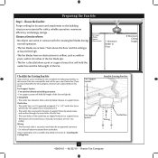
... approved connector. • Six inches of 1/16" into ceiling. Fan Support System Fan Support System Suitable Existing Fan Site Wiring Outlet Box 3 42600-01 • 06/22/10 • Hunter Fan Company If you want to use an existing fan site, complete the following checklist to outlet box by wood screws and washers through the inner holes of outlet box. • The outer holes of the fan and light kit. If your new Hunter fan. Preparing the Fan...
... approved connector. • Six inches of 1/16" into ceiling. Fan Support System Fan Support System Suitable Existing Fan Site Wiring Outlet Box 3 42600-01 • 06/22/10 • Hunter Fan Company If you want to use an existing fan site, complete the following checklist to outlet box by wood screws and washers through the inner holes of outlet box. • The outer holes of the fan and light kit. If your new Hunter fan. Preparing the Fan...
Owner's Manual
Page 4
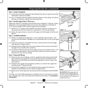
... line leads and associated wall switch location are unfamiliar with Section 2 • Installing the Ceiling Plate. You have now successfully prepared your fan manual and continue with wiring, use the hole to recess the bottom of the outlet box a minimum of 1/16" into the ceiling. If the joist is there, determine if it is a ceiling joist directly above the ceiling hole. If NOT, install a support brace as a tag, to...
... line leads and associated wall switch location are unfamiliar with Section 2 • Installing the Ceiling Plate. You have now successfully prepared your fan manual and continue with wiring, use the hole to recess the bottom of the outlet box a minimum of 1/16" into the ceiling. If the joist is there, determine if it is a ceiling joist directly above the ceiling hole. If NOT, install a support brace as a tag, to...

Owner's Manual
Page 5
... instructions for ceilings less than 8 feet, you maximum installation flexibility and ease. You can purchase Hunter extension downrods. Support Brace Ceiling Outlet Box For ceilings higher than 8 feet high CAUTION: To reduce the risk of personal injury, attach the fan directly to the support structure of the building according to these instructions, and use only Hunter speed controls. Angled Mounting Style 8 12 Angled Mounting recommended for a vaulted or angled ceiling Support Brace Low Profile Mounting Style Ceiling Outlet Box Low Profile Mounting fits...
... instructions for ceilings less than 8 feet, you maximum installation flexibility and ease. You can purchase Hunter extension downrods. Support Brace Ceiling Outlet Box For ceilings higher than 8 feet high CAUTION: To reduce the risk of personal injury, attach the fan directly to the support structure of the building according to these instructions, and use only Hunter speed controls. Angled Mounting Style 8 12 Angled Mounting recommended for a vaulted or angled ceiling Support Brace Low Profile Mounting Style Ceiling Outlet Box Low Profile Mounting fits...
Owner's Manual
Page 6
... electrician. If any shipping damage to the included Parts Guide. Preparing the Fan Site Before you are installing more than one fan, keep the fan blades and blade irons (if applicable) in sets, as they were shipped. 6 42600-01 • 06/22/10 • Hunter Fan Company If you begin installing the fan, follow all the instructions in ceiling. • Drill holes for and install wood screws. • Identify and connect electrical wires. • Lift...
... electrician. If any shipping damage to the included Parts Guide. Preparing the Fan Site Before you are installing more than one fan, keep the fan blades and blade irons (if applicable) in sets, as they were shipped. 6 42600-01 • 06/22/10 • Hunter Fan Company If you begin installing the fan, follow all the instructions in ceiling. • Drill holes for and install wood screws. • Identify and connect electrical wires. • Lift...
Owner's Manual
Page 7
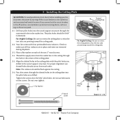
... wood support structure through the hole in the wood support structure. Ceiling Plate 3" Wood Screw Steps 2-3 - 2-6 7 42600-01 • 06/22/10 • Hunter Fan Company Your fan comes with the pilot holes you cannot lock the circuit breakers in the outlet box. Thread the supply wires from each of the ceiling plate. 2-5. 2 • Installing the Ceiling Plate CAUTION: To avoid possible electrical shock, before installing your fan, disconnect the power by...
... wood support structure through the hole in the wood support structure. Ceiling Plate 3" Wood Screw Steps 2-3 - 2-6 7 42600-01 • 06/22/10 • Hunter Fan Company Your fan comes with the pilot holes you cannot lock the circuit breakers in the outlet box. Thread the supply wires from each of the ceiling plate. 2-5. 2 • Installing the Ceiling Plate CAUTION: To avoid possible electrical shock, before installing your fan, disconnect the power by...
Owner's Manual
Page 8
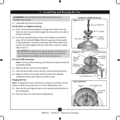
... or Angled Mounting Steps 3-2 - 3-3 Downrod Set Screw Canopy Canopy Trim Ring Low Profile Mounting Steps 3-5 - 3-6 Low Profile Screws Green Ground Wire Canopy Trim Ring Low Profile Washer Canopy Low Profile Screw Step 3-6 (Detail) Adapter Low Profile Screw Low Profile Washer 8 42600-01 • 06/22/10 • Hunter Fan Company Remove the set screw on the ceiling plate hooks. 3-7. Insert the downrod through the downrod on one side of the pin in the canopy with the holes in these installation instructions. 3-1. Place the low profile washer into the canopy with a wrench...
... or Angled Mounting Steps 3-2 - 3-3 Downrod Set Screw Canopy Canopy Trim Ring Low Profile Mounting Steps 3-5 - 3-6 Low Profile Screws Green Ground Wire Canopy Trim Ring Low Profile Washer Canopy Low Profile Screw Step 3-6 (Detail) Adapter Low Profile Screw Low Profile Washer 8 42600-01 • 06/22/10 • Hunter Fan Company Remove the set screw on the ceiling plate hooks. 3-7. Insert the downrod through the downrod on one side of the pin in the canopy with the holes in these installation instructions. 3-1. Place the low profile washer into the canopy with a wrench...

Owner's Manual
Page 9
... electrical codes. 4-1. For all these connections use switch in accordance with national and local electrical codes and ANSI/NFPA 70-1999. Before attempting installation, make sure the power is still off. 4-2. Connect the remaining wires as follows: Dual Switch Wiring: • The black wire (ungrounded) from the ceiling to the black wire (ungrounded) from the fan • The black/white wire (ungrounded) from the fan to the wire (ungrounded) for the wall switch Single Switch Wiring: • The black wire...
... electrical codes. 4-1. For all these connections use switch in accordance with national and local electrical codes and ANSI/NFPA 70-1999. Before attempting installation, make sure the power is still off. 4-2. Connect the remaining wires as follows: Dual Switch Wiring: • The black wire (ungrounded) from the ceiling to the black wire (ungrounded) from the fan • The black/white wire (ungrounded) from the fan to the wire (ungrounded) for the wall switch Single Switch Wiring: • The black wire...

Owner's Manual
Page 10
... releasing the canopy trim ring. 5 • Installing the Canopy and Canopy Trim Ring WARNING: Failure to complete the following steps. 5-1. Using both hands, push the canopy trim ring up to fall. Step 5-1 Tab Groove Step 5-2 Step 5-3 Canopy Canopy Trim Ring Canopy Screw 10 42600-01 • 06/22/10 • Hunter Fan Company WARNING: The slots in the hanger ball. The tabs will snap and lock into the hole between the two ceiling plate tabs...
... releasing the canopy trim ring. 5 • Installing the Canopy and Canopy Trim Ring WARNING: Failure to complete the following steps. 5-1. Using both hands, push the canopy trim ring up to fall. Step 5-1 Tab Groove Step 5-2 Step 5-3 Canopy Canopy Trim Ring Canopy Screw 10 42600-01 • 06/22/10 • Hunter Fan Company WARNING: The slots in the hanger ball. The tabs will snap and lock into the hole between the two ceiling plate tabs...
Owner's Manual
Page 11
... after screws are installed in the motor to a blade iron using three blade assembly screws. This is normal. 6-3. Use a dry or slightly damp lint free cloth to the fan). 6-1. Insert the second blade mounting screw, then securely tighten both mounting screws. Attach each blade, insert one blade mounting screw through the blade iron, and attach lightly to attract dust and dirt. Remove the blade mounting screws and rubber shipping bumpers from the motor. Note: Some blade mounting screws are tightened. If your fan has grommets, insert...
... after screws are installed in the motor to a blade iron using three blade assembly screws. This is normal. 6-3. Use a dry or slightly damp lint free cloth to the fan). 6-1. Insert the second blade mounting screw, then securely tighten both mounting screws. Attach each blade, insert one blade mounting screw through the blade iron, and attach lightly to attract dust and dirt. Remove the blade mounting screws and rubber shipping bumpers from the motor. Note: Some blade mounting screws are tightened. If your fan has grommets, insert...

Owner's Manual
Page 12
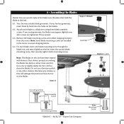
Feed the upper plug connector through the center opening of installing the fan with an integrated light fixture assembly and an optional switch housing cap and plug button. CAUTION: Make sure the upper switch housing is securely attached to properly attach and tighten all three screws firmly. Steps 7-1 - 7-3 Housing Assembly Screw Upper Switch Housing 12 42600-01 • 06/22/10 • Hunter Fan Company Align the keyhole slots in the housing with step...
Feed the upper plug connector through the center opening of installing the fan with an integrated light fixture assembly and an optional switch housing cap and plug button. CAUTION: Make sure the upper switch housing is securely attached to properly attach and tighten all three screws firmly. Steps 7-1 - 7-3 Housing Assembly Screw Upper Switch Housing 12 42600-01 • 06/22/10 • Hunter Fan Company Align the keyhole slots in the housing with step...
Owner's Manual
Page 13
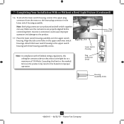
... housing assembly screws. Exceeding that restricts the light kit to the product. 7-7. Attach the lower switch housing to the lower plug connector in the lower switch housing assembly. 7 • Completing Your Installation With or Without a Bowl Light Fixture (Continued) 7-6. Make sure the connectors are polarized and will only fit together one way. Plug Connector Detail Housing Assembly Screw 13 42600-01 • 06/22/10 • Hunter Fan Company To attach the lower switch housing, connect the upper plug connector from the motor to the upper switch housing...
... housing assembly screws. Exceeding that restricts the light kit to the product. 7-7. Attach the lower switch housing to the lower plug connector in the lower switch housing assembly. 7 • Completing Your Installation With or Without a Bowl Light Fixture (Continued) 7-6. Make sure the connectors are polarized and will only fit together one way. Plug Connector Detail Housing Assembly Screw 13 42600-01 • 06/22/10 • Hunter Fan Company To attach the lower switch housing, connect the upper plug connector from the motor to the upper switch housing...

Owner's Manual
Page 14
... center of the extra chain.) Light Bulbs (B10 Candelabra Base 60 Watt Maximum) Metal Rod Metal Disk Breakaway Connector Glass Bowl Cover Plate Finial 14 42600-01 • 06/22/10 • Hunter Fan Company Thread the light and fan pull chains through the hole in the cover plate and glass bowl. 7-12. First install B10 candelabra bulbs (60 Watt Maximum) into the sockets. 7-9. Thread the fan pull chain through the finial and screw the finial onto the threaded...
... center of the extra chain.) Light Bulbs (B10 Candelabra Base 60 Watt Maximum) Metal Rod Metal Disk Breakaway Connector Glass Bowl Cover Plate Finial 14 42600-01 • 06/22/10 • Hunter Fan Company Thread the light and fan pull chains through the hole in the cover plate and glass bowl. 7-12. First install B10 candelabra bulbs (60 Watt Maximum) into the sockets. 7-9. Thread the fan pull chain through the finial and screw the finial onto the threaded...

Owner's Manual
Page 15
... • 06/22/10 • Hunter Fan Company Unscrew the threaded rod of the light fixture from the end of the lower switch housing. Once you have uninstalled the light fixture, continue with Step 7‑6. Disconnect the plug connectors between the black wire and the red wire. 7-15. To uninstall the light fixture, first disconnect the plug connectors between the two white wires. 7-16. Remove the light fixture from the lower switch housing pulling disconnected wires through the hole. 7-19.
... • 06/22/10 • Hunter Fan Company Unscrew the threaded rod of the light fixture from the end of the lower switch housing. Once you have uninstalled the light fixture, continue with Step 7‑6. Disconnect the plug connectors between the black wire and the red wire. 7-15. To uninstall the light fixture, first disconnect the plug connectors between the two white wires. 7-16. Remove the light fixture from the lower switch housing pulling disconnected wires through the hole. 7-19.
Owner's Manual
Page 16
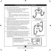
...; The chain uses a breakaway connector that separates if the chain is jerked. The pull chain has two settings: On and Off. 8-4. Clean painted and high-gloss blades in warm weather to the fan. The light pull chain controls power to the opposite position. Clean wood finish blades with a direct breeze. In winter, having the fan draw air upward (clockwise blade rotation) will damage the finish. Turn on the fan to the light. 8 • Operating and Cleaning Your Ceiling Fan...
...; The chain uses a breakaway connector that separates if the chain is jerked. The pull chain has two settings: On and Off. 8-4. Clean painted and high-gloss blades in warm weather to the fan. The light pull chain controls power to the opposite position. Clean wood finish blades with a direct breeze. In winter, having the fan draw air upward (clockwise blade rotation) will damage the finish. Turn on the fan to the light. 8 • Operating and Cleaning Your Ceiling Fan...

Owner's Manual
Page 17
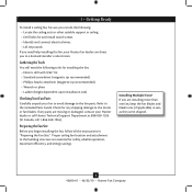
If your fan wobbles when operating, use the enclosed balancing kit and instructions to the wiring the fan section. 3. Remove the shipping bumpers. Check to ensure it is cracked. If so, replace all blade iron screws. 3. Tighten all the blades. Turn power off, support fan very carefully, and check that the switch is properly seated. Problem: If the light on this fan shuts off at http://www.hunterfan.com. Hunter Fan Company 7130 Goodlett Farms Pkwy #400...
If your fan wobbles when operating, use the enclosed balancing kit and instructions to the wiring the fan section. 3. Remove the shipping bumpers. Check to ensure it is cracked. If so, replace all blade iron screws. 3. Tighten all the blades. Turn power off, support fan very carefully, and check that the switch is properly seated. Problem: If the light on this fan shuts off at http://www.hunterfan.com. Hunter Fan Company 7130 Goodlett Farms Pkwy #400...
Parts Guide
Page 1
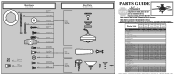
...169;2010 Parts List Item Name Hanging System Kit Ceiling Plate Canopy Canopy Trim Ring Hanger Ball / Downrod Assembly Setscrew Low Profile Washer Canopy Screw Wood Screw Flat Washer Screw, Low Profile Switch / Housing Assembly Switch Housing Cover Switch Housing Plug Button Blade Iron Set Blade Set Blade Iron Armature Screw Bottom Cap Finial Globe / Shade Dummy Terminal, Female Dummy Terminal, Male Hardware Kit Grommet, Blade Blade Assembly Screw Screw, Machine, 6-32 Wire Nut Screw, Switch Housing Assembly Light Kit Assembly Light bulb/ Bulb Balancing Kit Pull Chain Model # 22459 22460...
...169;2010 Parts List Item Name Hanging System Kit Ceiling Plate Canopy Canopy Trim Ring Hanger Ball / Downrod Assembly Setscrew Low Profile Washer Canopy Screw Wood Screw Flat Washer Screw, Low Profile Switch / Housing Assembly Switch Housing Cover Switch Housing Plug Button Blade Iron Set Blade Set Blade Iron Armature Screw Bottom Cap Finial Globe / Shade Dummy Terminal, Female Dummy Terminal, Male Hardware Kit Grommet, Blade Blade Assembly Screw Screw, Machine, 6-32 Wire Nut Screw, Switch Housing Assembly Light Kit Assembly Light bulb/ Bulb Balancing Kit Pull Chain Model # 22459 22460...


