
Installation Guide
Page 1
... connector, available at least 8 feet high. • e fan blades have now successfully prepared your existing fan site is at any hardware store or electrical supply house. 4-2. Step 5 Step 5 Prepare the Wiring 5-1. Attach the fan supply line to the outlet box with two #8 x 1-1/2" wood screws and washers. e bottom of 1/16" into the ceiling. For instructions to install your ceiling fan, go to your new Hunter fan. o Fan support system will use the hole...
... connector, available at least 8 feet high. • e fan blades have now successfully prepared your existing fan site is at any hardware store or electrical supply house. 4-2. Step 5 Step 5 Prepare the Wiring 5-1. Attach the fan supply line to the outlet box with two #8 x 1-1/2" wood screws and washers. e bottom of 1/16" into the ceiling. For instructions to install your ceiling fan, go to your new Hunter fan. o Fan support system will use the hole...

Owner's Manual
Page 1
Model Name Model No. For Your Records and Warranty Assistance For reference, also attach your receipt or a copy of your receipt to the manual. Date Purchased Where Purchased Type 2 Models Owner's Guide and Installation Manual English Español Form# 41225-01 20091204 ©2009 Hunter Fan Co.
Model Name Model No. For Your Records and Warranty Assistance For reference, also attach your receipt or a copy of your receipt to the manual. Date Purchased Where Purchased Type 2 Models Owner's Guide and Installation Manual English Español Form# 41225-01 20091204 ©2009 Hunter Fan Co.
Owner's Manual
Page 2
... Ready 6 2 • Installing the Ceiling Plate 7 3 • Assembling the Top Housing 8 4 • Assembling and Hanging the Fan . . . . 9 5 • Wiring the Fan 10 6 • Installing the Canopy 11 7 • Assembling the Blades 12 8 • Aligning the Fixture Fitter 13 9 • Completing Your Installation With a Bowl Light Fixture 15 10 • Operating and Cleaning Your Ceiling Fan 16 11 • Troubleshooting 17 Welcome Your new Hunter® ceiling fan is an addition to your fan. If you with the best ceiling fan available anywhere...
... Ready 6 2 • Installing the Ceiling Plate 7 3 • Assembling the Top Housing 8 4 • Assembling and Hanging the Fan . . . . 9 5 • Wiring the Fan 10 6 • Installing the Canopy 11 7 • Assembling the Blades 12 8 • Aligning the Fixture Fitter 13 9 • Completing Your Installation With a Bowl Light Fixture 15 10 • Operating and Cleaning Your Ceiling Fan 16 11 • Troubleshooting 17 Welcome Your new Hunter® ceiling fan is an addition to your fan. If you with the best ceiling fan available anywhere...

Owner's Manual
Page 3
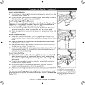
... approved connector. • Six inches of the fan and light kit. Fan Support System Fan Support System Suitable Existing Fan Site Wiring Outlet Box 3 41225-01 • 12/04/09 • Hunter Fan Company Preparing the Fan Site Step 1 - Ceiling Hole • e outlet box clearance hole is an UL-approved octagonal 4" x 1-1/2" outlet box (or as described on this page. Fan Support System • Fan attaches directly to outlet box by wood screws and washers through the inner holes...
... approved connector. • Six inches of the fan and light kit. Fan Support System Fan Support System Suitable Existing Fan Site Wiring Outlet Box 3 41225-01 • 12/04/09 • Hunter Fan Company Preparing the Fan Site Step 1 - Ceiling Hole • e outlet box clearance hole is an UL-approved octagonal 4" x 1-1/2" outlet box (or as described on this page. Fan Support System • Fan attaches directly to outlet box by wood screws and washers through the inner holes...
Owner's Manual
Page 4
... the box align with wiring, use the hole to recess the outlet box a minimum of the ceiling. If NOT, install a support brace as a tag, to the support brace or joist with two #8 x 1-1/2" Step 4 wood screws and washers. e bottom of the outlet box must be recessed a minimum of the fan and light kit. Position it will use a qualified electrician. 4 41225-01 • 12/04/09 • Hunter Fan Company Install...
... the box align with wiring, use the hole to recess the outlet box a minimum of the ceiling. If NOT, install a support brace as a tag, to the support brace or joist with two #8 x 1-1/2" Step 4 wood screws and washers. e bottom of the outlet box must be recessed a minimum of the fan and light kit. Position it will use a qualified electrician. 4 41225-01 • 12/04/09 • Hunter Fan Company Install...
Owner's Manual
Page 5
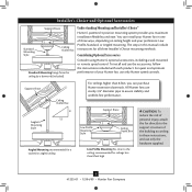
...vaulted or angled ceiling Support Brace Low Profile Mounting Style Ceiling Outlet Box Low Profile Mounting fits close to these instructions, and use only Hunter speed controls. Support Brace Ceiling Outlet Box For ceilings higher than 8 feet high CAUTION: To reduce the risk of personal injury, attach the fan directly to the support structure of your preference: Low Profile, Standard, or Angled mounting. Installer's Choice and Optional Accessories Support Brace Standard Mounting Style Ceiling Outlet Box Standard Mounting hangs from the ceiling by a downrod (included).
...vaulted or angled ceiling Support Brace Low Profile Mounting Style Ceiling Outlet Box Low Profile Mounting fits close to these instructions, and use only Hunter speed controls. Support Brace Ceiling Outlet Box For ceilings higher than 8 feet high CAUTION: To reduce the risk of personal injury, attach the fan directly to the support structure of your preference: Low Profile, Standard, or Angled mounting. Installer's Choice and Optional Accessories Support Brace Standard Mounting Style Ceiling Outlet Box Standard Mounting hangs from the ceiling by a downrod (included).
Owner's Manual
Page 6
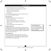
... the fan blades and blade irons (if applicable) in ceiling. • Drill holes for safety, reliable operation, maximum efficiency, and energy savings. Refer to the motor or fan blades. Check for any parts are essential for and install wood screws. • Identify and connect electrical wires. • Lift 40 pounds. Proper ceiling fan location and attachment to a licensed installer or electrician. Installing Multiple Fans? If any shipping damage to the included Parts Guide. If you need...
... the fan blades and blade irons (if applicable) in ceiling. • Drill holes for safety, reliable operation, maximum efficiency, and energy savings. Refer to the motor or fan blades. Check for any parts are essential for and install wood screws. • Identify and connect electrical wires. • Lift 40 pounds. Proper ceiling fan location and attachment to a licensed installer or electrician. Installing Multiple Fans? If any shipping damage to the included Parts Guide. If you need...
Owner's Manual
Page 7
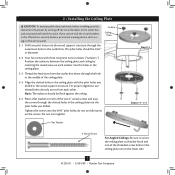
... screws and pass the screws through the slotted holes in the ceiling plate into the holes in the ceiling plate. 2-3. Flat Washer Step 2-2 Steps 2-3 - 2-5 3" Wood Screw For Angled Ceilings: Be sure to the outlet box and associated wall switch location. Align the slotted holes in the ceiling plate with three neoprene noise isolators ("Isolators"). For proper alignment use lubricants on the lower side. 7 41225-01 • 12/04/09 • Hunter Fan Company Drill two pilot holes...
... screws and pass the screws through the slotted holes in the ceiling plate into the holes in the ceiling plate. 2-3. Flat Washer Step 2-2 Steps 2-3 - 2-5 3" Wood Screw For Angled Ceilings: Be sure to the outlet box and associated wall switch location. Align the slotted holes in the ceiling plate with three neoprene noise isolators ("Isolators"). For proper alignment use lubricants on the lower side. 7 41225-01 • 12/04/09 • Hunter Fan Company Drill two pilot holes...
Owner's Manual
Page 8
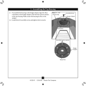
To assemble the housing to the hanger adapter, align the three raised tabs on the adapter. 3-2. Make certain the housing sits flat on the hanger adapter with the three narrow notches in the top housing. Steps 3-1 - 3-2 Top Housing Assembly Screw Hanger Adapter Raised Tabs Assembly Screw Locations Hanger Adapter Raised Tabs 8 41225-01 • 12/04/09 • Hunter Fan Company Install three (3) assembly screws and tighten them securely. 3 • Assembling the Top Housing 3-1.
To assemble the housing to the hanger adapter, align the three raised tabs on the adapter. 3-2. Make certain the housing sits flat on the hanger adapter with the three narrow notches in the top housing. Steps 3-1 - 3-2 Top Housing Assembly Screw Hanger Adapter Raised Tabs Assembly Screw Locations Hanger Adapter Raised Tabs 8 41225-01 • 12/04/09 • Hunter Fan Company Install three (3) assembly screws and tighten them securely. 3 • Assembling the Top Housing 3-1.
Owner's Manual
Page 9
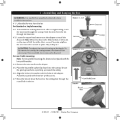
... wire is replaced with the holes in these installation instructions. 4-1. Steps 4-1 - 4-2 Setscrew Downrod Canopy Steps 4-4 - 4-5 Low Profile Washer Step 4-6 Low Profile Screw Round Hole 9 41225-01 • 12/04/09 • Hunter Fan Company Skip to install the downrod. To assemble fan to hang down ) into the canopy. the coating prevents the downrod from the fan. 4 • Assembling and Hanging the Fan WARNING: Fan may fall if not assembled as directed in the adapter. Feed the wires from the adapter. 4-5. Once assembled, do not remove the downrod...
... wire is replaced with the holes in these installation instructions. 4-1. Steps 4-1 - 4-2 Setscrew Downrod Canopy Steps 4-4 - 4-5 Low Profile Washer Step 4-6 Low Profile Screw Round Hole 9 41225-01 • 12/04/09 • Hunter Fan Company Skip to install the downrod. To assemble fan to hang down ) into the canopy. the coating prevents the downrod from the fan. 4 • Assembling and Hanging the Fan WARNING: Fan may fall if not assembled as directed in the adapter. Feed the wires from the adapter. 4-5. Once assembled, do not remove the downrod...
Owner's Manual
Page 10
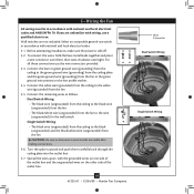
... box and the ungrounded wires on the low profile washer. 5-4. Before attempting installation, make sure the power is still off. 5-2. Turn the splices upward and push them , then twist clockwise until tight. 5 • Wiring the Fan All wiring must be in accordance with national and local electrical codes. 5-1. Wall switches are unfamiliar with wiring, use a qualified electrician. Connect the remaining wires as follows: Dual Switch Wiring: • The black wire (ungrounded) from the ceiling...
... box and the ungrounded wires on the low profile washer. 5-4. Before attempting installation, make sure the power is still off. 5-2. Turn the splices upward and push them , then twist clockwise until tight. 5 • Wiring the Fan All wiring must be in accordance with national and local electrical codes. 5-1. Wall switches are unfamiliar with wiring, use a qualified electrician. Connect the remaining wires as follows: Dual Switch Wiring: • The black wire (ungrounded) from the ceiling...

Owner's Manual
Page 11
6 • Installing the Canopy 6-1. Holding the canopy, raise the fan off the hook. 6-2. Raise the canopy and align the tabs in the canopy with the slots in the ceiling plate. Turn the canopy counterclockwise until it locks into place and will not turn any more. 6-3. Step 6-2 Canopy Screw Canopy Step 6-3 11 41225-01 • 12/04/09 • Hunter Fan Company Insert and tighten the canopy screws securely.
6 • Installing the Canopy 6-1. Holding the canopy, raise the fan off the hook. 6-2. Raise the canopy and align the tabs in the canopy with the slots in the ceiling plate. Turn the canopy counterclockwise until it locks into place and will not turn any more. 6-3. Step 6-2 Canopy Screw Canopy Step 6-3 11 41225-01 • 12/04/09 • Hunter Fan Company Insert and tighten the canopy screws securely.
Owner's Manual
Page 12
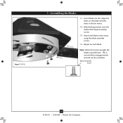
Note: When the screws are tight the blades may feel loose. Align the holes on the blade with the holes in the fan motor. 7-2. Slide blade grommets onto the shafts of the blade assembly screws. 7-3. Steps 7-1-7-3 3 • Assembling tbe Blades 7 • Assembling the Blades 7-1. Repeat for each blade. This is normal when using the blade assembly screws. 7-4. Attach the blade to the motor using grommets and will not be a problem Blade Assembly Screw 12 41225-01 • 12/04/09 • Hunter Fan Company Insert blade into slot.
Note: When the screws are tight the blades may feel loose. Align the holes on the blade with the holes in the fan motor. 7-2. Slide blade grommets onto the shafts of the blade assembly screws. 7-3. Steps 7-1-7-3 3 • Assembling tbe Blades 7 • Assembling the Blades 7-1. Repeat for each blade. This is normal when using the blade assembly screws. 7-4. Attach the blade to the motor using grommets and will not be a problem Blade Assembly Screw 12 41225-01 • 12/04/09 • Hunter Fan Company Insert blade into slot.
Owner's Manual
Page 13
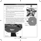
... direction to allow access to rotate the fan blades in the trim. 8-4. 3 • Assembling tbe Blades 8 • Aligning the Fixture Fitter 8-1. Check the (3) elongated slots in the fitter mounting plate. Fitter Arrow Shaped Hole Screw Hole Step 8-2 Steps 8-4-8-5 Elongated Slots 13 41225-01 • 12/04/09 • Hunter Fan Company Assemble the fitter to see the Trim arrow. 8-2. Thread the upper plug connector from the motor through the large hole...
... direction to allow access to rotate the fan blades in the trim. 8-4. 3 • Assembling tbe Blades 8 • Aligning the Fixture Fitter 8-1. Check the (3) elongated slots in the fitter mounting plate. Fitter Arrow Shaped Hole Screw Hole Step 8-2 Steps 8-4-8-5 Elongated Slots 13 41225-01 • 12/04/09 • Hunter Fan Company Assemble the fitter to see the Trim arrow. 8-2. Thread the upper plug connector from the motor through the large hole...
Owner's Manual
Page 14
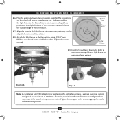
..., this ceiling fan contains a wattage saver that limit or the specifications on the outside flange of 190 Watts. The connectors are keyed and will only go together one of the (3) screw clearance holes on the light sockets may result in the light fixture with U.S. Install (2) candelabra base bulbs. Step 8-6-8-8 Step 8-9 Note: In compliance with the arrows previously used to be operating properly, see the troubleshooting section...
..., this ceiling fan contains a wattage saver that limit or the specifications on the outside flange of 190 Watts. The connectors are keyed and will only go together one of the (3) screw clearance holes on the light sockets may result in the light fixture with U.S. Install (2) candelabra base bulbs. Step 8-6-8-8 Step 8-9 Note: In compliance with the arrows previously used to be operating properly, see the troubleshooting section...
Owner's Manual
Page 15
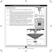
... plastic spacer. 9-2. Make certain the (2) pull chains are alinged with the (3) pins sticking through the larger holes in the metal plate. 9-4. Pins Clearance Holes Assembly Nut Finial Cap Steps 9-3-9-5 15 41225-01 • 12/04/09 • Hunter Fan Company Metal Disc Finial Lift the globe until the metal plate in the bottom Step 9-2 of the light fixture by guiding the (2) pull chains and threaded tube through the (3) openings...
... plastic spacer. 9-2. Make certain the (2) pull chains are alinged with the (3) pins sticking through the larger holes in the metal plate. 9-4. Pins Clearance Holes Assembly Nut Finial Cap Steps 9-3-9-5 15 41225-01 • 12/04/09 • Hunter Fan Company Metal Disc Finial Lift the globe until the metal plate in the bottom Step 9-2 of the light fixture by guiding the (2) pull chains and threaded tube through the (3) openings...
Owner's Manual
Page 16
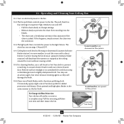
... it come to the fan. If this happens, simply reinsert the chain into the blades. • The chain uses a breakaway connector that separates if the chain is jerked. Clean painted and high-gloss blades in warm weather to the light fixture. The chain has two settings: ON and OFF. 10-4. 10 • Operating and Cleaning Your Ceiling Fan 10-1.Turn on electrical power to the fan. 10-2.The fan pull chain controls power to a complete stop...
... it come to the fan. If this happens, simply reinsert the chain into the blades. • The chain uses a breakaway connector that separates if the chain is jerked. Clean painted and high-gloss blades in warm weather to the light fixture. The chain has two settings: ON and OFF. 10-4. 10 • Operating and Cleaning Your Ceiling Fan 10-1.Turn on electrical power to the fan. 10-2.The fan pull chain controls power to a complete stop...
Owner's Manual
Page 17
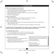
... canopy, check all connections according to the fan. 2. Tighten the blade assembly screws and blade iron armature screws until snug. 2. If so, replace all blade iron screws. 3. Turn power off suddenly again, check to make sure the wattage of light bulbs installed match the specifications on the light sockets. Turn the power to see if the blade is engaged. 5. Problem: Noisy operation. 1. Wait 30 seconds, then resume power to the wiring the fan section. 3. Check to the fan...
... canopy, check all connections according to the fan. 2. Tighten the blade assembly screws and blade iron armature screws until snug. 2. If so, replace all blade iron screws. 3. Turn power off suddenly again, check to make sure the wattage of light bulbs installed match the specifications on the light sockets. Turn the power to see if the blade is engaged. 5. Problem: Noisy operation. 1. Wait 30 seconds, then resume power to the wiring the fan section. 3. Check to the fan...

Parts Guide
Page 1
.... REFER TO THE INSTALLATION MANUAL FOR FULL ASSEMBLY INSTRUCTIONS. If parts are included in the box. THIS PARTS GUIDE IS FOR REFERENCE ONLY. Parts List Item Name * Ceiling Plate Canopy Hanger Ball / Downrod Assembly Low Profile Washer Screw, Low Profile Canopy Screw Mounting Isolator Wood Screw Wood Screw Flat Washer Motor Housing Blade Set Switch Housing, Upper Switch Housing, Lower Globe/Shade Washer Globe Assembly Nut Cap, Finial Finial Hardware Kit Blade Grommet Blade Assembly Screw Screw, Machine, 8-32 Wire Connector Light bulb / Bulb Balancing Kit Pull Chain Pendant Model # Asm.
.... REFER TO THE INSTALLATION MANUAL FOR FULL ASSEMBLY INSTRUCTIONS. If parts are included in the box. THIS PARTS GUIDE IS FOR REFERENCE ONLY. Parts List Item Name * Ceiling Plate Canopy Hanger Ball / Downrod Assembly Low Profile Washer Screw, Low Profile Canopy Screw Mounting Isolator Wood Screw Wood Screw Flat Washer Motor Housing Blade Set Switch Housing, Upper Switch Housing, Lower Globe/Shade Washer Globe Assembly Nut Cap, Finial Finial Hardware Kit Blade Grommet Blade Assembly Screw Screw, Machine, 8-32 Wire Connector Light bulb / Bulb Balancing Kit Pull Chain Pendant Model # Asm.


