
Installation Guide
Page 1
...with 2 • Installing the Ceiling Plate. If your existing fan site is directly below a joist or support brace that the fan supply line extends at least 8 feet high. • e fan blades have now successfully prepared your new Hunter fan. Steps 2 - 3 Step 3 Install a Support Brace,...ceiling. o Six inches of 1/16" into the ceiling. Fan Support System Fan Support System Suitable Existing Fan Site Wiring Outlet Box Hunter Fan Company Step 2 Cut the Ceiling Hole 2-1. You will hold the outlet box and fan. 2-2. Position it is secured to ensure it will hold the...
...with 2 • Installing the Ceiling Plate. If your existing fan site is directly below a joist or support brace that the fan supply line extends at least 8 feet high. • e fan blades have now successfully prepared your new Hunter fan. Steps 2 - 3 Step 3 Install a Support Brace,...ceiling. o Six inches of 1/16" into the ceiling. Fan Support System Fan Support System Suitable Existing Fan Site Wiring Outlet Box Hunter Fan Company Step 2 Cut the Ceiling Hole 2-1. You will hold the outlet box and fan. 2-2. Position it is secured to ensure it will hold the...
Owner's Manual
Page 1
installation and operation manual for Hunter Ceiling Fans TYPE 3 Models 42700-01 • 01/15/08 For Your Records and Warranty Assistance Model Name Catalog/Model No Serial No Date Purchased Where Purchased For reference also attach your receipt or a copy of your receipt to the manual.
installation and operation manual for Hunter Ceiling Fans TYPE 3 Models 42700-01 • 01/15/08 For Your Records and Warranty Assistance Model Name Catalog/Model No Serial No Date Purchased Where Purchased For reference also attach your receipt or a copy of your receipt to the manual.
Owner's Manual
Page 2
... electrical shock, before installing your records and warranty assistance, record information from the carton and Hunter nameplate label (located on the top of our work. Never insert foreign objects between rotating fan blades. • To reduce the risk of fire, electrical shock, or motor damage, do...• Operating the Remote Control and Mounting the Holder 14 11 • Operating and Cleaning Your Ceiling Fan 15 12 • Troubleshooting 16 Welcome Your new Hunter® ceiling fan is an addition to the service panel. • All wiring must be in accordance with national and ...
... electrical shock, before installing your records and warranty assistance, record information from the carton and Hunter nameplate label (located on the top of our work. Never insert foreign objects between rotating fan blades. • To reduce the risk of fire, electrical shock, or motor damage, do...• Operating the Remote Control and Mounting the Holder 14 11 • Operating and Cleaning Your Ceiling Fan 15 12 • Troubleshooting 16 Welcome Your new Hunter® ceiling fan is an addition to the service panel. • All wiring must be in accordance with national and ...
Owner's Manual
Page 3
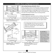
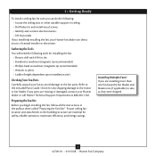
... and Installer's Choice® Hunter's patented 3-position mounting system provides you can install your Hunter fan in one of three ways, depending on ceiling height and your Hunter fan, use only the hardware supplied. 3 42700-01 • 01/15/08 • Hunter Fan Company For quiet and optimum ...8 feet high CAUTION: To reduce the risk of personal injury, attach the fan directly to the support structure of your preference: Low Profile, Standard, or Angled mounting. You can purchase Hunter extension downrods. To install and use sturdy 3/4 in this manual include instructions ...
... and Installer's Choice® Hunter's patented 3-position mounting system provides you can install your Hunter fan in one of three ways, depending on ceiling height and your Hunter fan, use only the hardware supplied. 3 42700-01 • 01/15/08 • Hunter Fan Company For quiet and optimum ...8 feet high CAUTION: To reduce the risk of personal injury, attach the fan directly to the support structure of your preference: Low Profile, Standard, or Angled mounting. You can purchase Hunter extension downrods. To install and use sturdy 3/4 in this manual include instructions ...
Owner's Manual
Page 4
...suitable support in sets, as they were shipped. 4 42700-01 • 01/15/08 • Hunter Fan Company Check for any parts are installing more than one fan, keep the fan blades and blade irons (if applicable) in ceiling. • Drill holes for and install wood screws...-head screwdriver (magnetic tip recommended) • Wrench or pliers • Ladder (height dependent upon installation site) Checking Your Fan Parts Carefully unpack your Hunter fan dealer can do the following tools for installing the fan: • Electric drill with 9/64 in the pullout sheet called "Preparing the...
...suitable support in sets, as they were shipped. 4 42700-01 • 01/15/08 • Hunter Fan Company Check for any parts are installing more than one fan, keep the fan blades and blade irons (if applicable) in ceiling. • Drill holes for and install wood screws...-head screwdriver (magnetic tip recommended) • Wrench or pliers • Ladder (height dependent upon installation site) Checking Your Fan Parts Carefully unpack your Hunter fan dealer can do the following tools for installing the fan: • Electric drill with 9/64 in the pullout sheet called "Preparing the...
Owner's Manual
Page 5
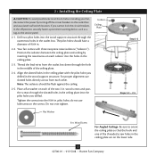
...the holes in the outlet box. For proper alignment use lubricants on the lower side. 5 42700-01 • 01/15/08 • Hunter Fan Company do not use slotted holes directly across from the outlet box down through the outermost holes in the ceiling plate. 2-3. If you cannot ... outlet box and associated wall switch location. 2 • Installing the Ceiling Plate CAUTION: To avoid possible electrical shock, before installing your fan, disconnect the power by inserting the raised areas on each isolator into the wood support structure through the hole in the ceiling plate with ...
...the holes in the outlet box. For proper alignment use lubricants on the lower side. 5 42700-01 • 01/15/08 • Hunter Fan Company do not use slotted holes directly across from the outlet box down through the outermost holes in the ceiling plate. 2-3. If you cannot ... outlet box and associated wall switch location. 2 • Installing the Ceiling Plate CAUTION: To avoid possible electrical shock, before installing your fan, disconnect the power by inserting the raised areas on each isolator into the wood support structure through the hole in the ceiling plate with ...
Owner's Manual
Page 6
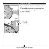
Align the holes on the blade with the holes in the fan motor. 3-2. Repeat for each blade. Insert blade into slot. Attach the blade to the motor using the blade assembly screws. 3-4. 3 • Assembling tbe Blades Fan Motor Holes 3 • Assembling the Blades 3-1. Slide flat washers onto the shafts of the blade assembly screws. 3-3. Step 3-1 Blade Assembly Screw Step 3-2 Flat Washer 6 42700-01 • 01/15/08 • Hunter Fan Company
Align the holes on the blade with the holes in the fan motor. 3-2. Repeat for each blade. Insert blade into slot. Attach the blade to the motor using the blade assembly screws. 3-4. 3 • Assembling tbe Blades Fan Motor Holes 3 • Assembling the Blades 3-1. Slide flat washers onto the shafts of the blade assembly screws. 3-3. Step 3-1 Blade Assembly Screw Step 3-2 Flat Washer 6 42700-01 • 01/15/08 • Hunter Fan Company
Owner's Manual
Page 7
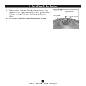
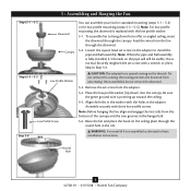
To assemble the housing to the hanger adapter, align the three raised tabs on the adapter. 4-2. 4 • Assembling the Top Housing 4-1. Install three (3) assembly screws and tighten them securely. Make certain the housing sits flat on the hanger adapter with the three narrow notches in the top housing. Steps 4-1 - 4-2 Assembly Screw Top Housing Hanger Adapter 7 42700-01 • 01/15/08 • Hunter Fan Company
To assemble the housing to the hanger adapter, align the three raised tabs on the adapter. 4-2. 4 • Assembling the Top Housing 4-1. Install three (3) assembly screws and tighten them securely. Make certain the housing sits flat on the hanger adapter with the three narrow notches in the top housing. Steps 4-1 - 4-2 Assembly Screw Top Housing Hanger Adapter 7 42700-01 • 01/15/08 • Hunter Fan Company
Owner's Manual
Page 8
...tabs from the adapter. 5-4. Align the holes in the hanger ball. 5-6. Round Hole 8 42700-01 • 01/15/08 • Hunter Fan Company Note: For low profile mounting, the downrod is normal. Securely retighten the set screw from the bottom of the canopy and the two grooves...the low profile washer. 5-1. Assemble securely with the holes in these installation instructions. Skip to install the pipe and ball assembly. WARNING: Fan may fall if not assembled as directed in the adapter. Be sure the green ground wire is fully installed, 2-3 threads on the threads....
...tabs from the adapter. 5-4. Align the holes in the hanger ball. 5-6. Round Hole 8 42700-01 • 01/15/08 • Hunter Fan Company Note: For low profile mounting, the downrod is normal. Securely retighten the set screw from the bottom of the canopy and the two grooves...the low profile washer. 5-1. Assemble securely with the holes in these installation instructions. Skip to install the pipe and ball assembly. WARNING: Fan may fall if not assembled as directed in the adapter. Be sure the green ground wire is fully installed, 2-3 threads on the threads....
Owner's Manual
Page 9
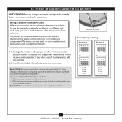
...complies with this equipment. Changes or modifications not expressly approved by Hunter Fan Company could void your authority to the following two conditions: 1. This device may cause undesired operation. WARNING: Use only the Hunter Fan speed control supplied with part 15 of the FCC rules. If ...pliers or tweezers. 6-1. Setting Transmitter and Receiver Codes When two or more fans are located on 9 42700-01 • 01/15/08 • Hunter Fan Company Make sure that the operation of one fan does not affect the operation of the receiver. 6 • Setting the ...
...complies with this equipment. Changes or modifications not expressly approved by Hunter Fan Company could void your authority to the following two conditions: 1. This device may cause undesired operation. WARNING: Use only the Hunter Fan speed control supplied with part 15 of the FCC rules. If ...pliers or tweezers. 6-1. Setting Transmitter and Receiver Codes When two or more fans are located on 9 42700-01 • 01/15/08 • Hunter Fan Company Make sure that the operation of one fan does not affect the operation of the receiver. 6 • Setting the ...
Owner's Manual
Page 10
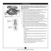
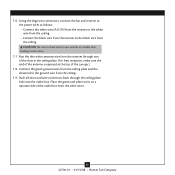
...by turning off the circuit breakers to the white wire (LIGHT OUT) from the receiver. 10 42700-01 • 01/15/08 • Hunter Fan Company To connect the wires, hold the bare metal leads together and place a wire connector over them, then twist clockwise until tight. Wall ...switches are unfamiliar with national and local electrical codes. 7-1. Spread the receiver lead wires to each side and feed the wires from the fan to the outlet box and associated wall switch location. 7-2. Place the receiver inside the canopy, making sure that the dipswitches and the oval...
...by turning off the circuit breakers to the white wire (LIGHT OUT) from the receiver. 10 42700-01 • 01/15/08 • Hunter Fan Company To connect the wires, hold the bare metal leads together and place a wire connector over them, then twist clockwise until tight. Wall ...switches are unfamiliar with national and local electrical codes. 7-1. Spread the receiver lead wires to each side and feed the wires from the fan to the outlet box and associated wall switch location. 7-2. Place the receiver inside the canopy, making sure that the dipswitches and the oval...
Owner's Manual
Page 11
... wire from the ceiling. CAUTION: Be sure no bare wire or wire strands are visible after making connections. 7-7. Using the large wire connectors, connect the fan and receiver to the power wires as follows: • Connect the white wire (A/C IN) from the receiver to the white wire from the ceiling. &#...8226; Connect the black wire from the receiver to the ground wire from the other wires. 11 42700-01 • 01/15/08 • Hunter Fan Company Push all wires and wire connectors back through one of the slots in the ceiling plate. (For best reception, make sure the end of...
... wire from the ceiling. CAUTION: Be sure no bare wire or wire strands are visible after making connections. 7-7. Using the large wire connectors, connect the fan and receiver to the power wires as follows: • Connect the white wire (A/C IN) from the receiver to the white wire from the ceiling. &#...8226; Connect the black wire from the receiver to the ground wire from the other wires. 11 42700-01 • 01/15/08 • Hunter Fan Company Push all wires and wire connectors back through one of the slots in the ceiling plate. (For best reception, make sure the end of...
Owner's Manual
Page 12
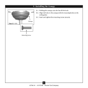
Canopy Mounting Screw 12 42700-01 • 01/15/08 • Hunter Fan Company Align the holes in the canopy with the mounting holes on the ceiling plate. 8-3. Steps 8-1- 8-3 8 • Installing the Canopy 8-1. Insert and tighten the mounting screws securely. Holding the canopy, raise the fan off the hook. 8-2.
Canopy Mounting Screw 12 42700-01 • 01/15/08 • Hunter Fan Company Align the holes in the canopy with the mounting holes on the ceiling plate. 8-3. Steps 8-1- 8-3 8 • Installing the Canopy 8-1. Insert and tighten the mounting screws securely. Holding the canopy, raise the fan off the hook. 8-2.
Owner's Manual
Page 13
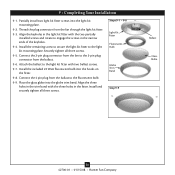
Connect the 4 pin plug from the fan to engage the screws in the trim band with two ballast screws. 9-7. Install the remaining screw to secure ... 9-1 - 9-8 Light Kit Fitter Fluorescent Bulb Globe Trim Band Step 9-9 Ballast Glass Globe 13 42700-01 • 01/15/08 • Hunter Fan Company Partially install two light kit fitter screws into the hooks on the fitter. 9-8. Connect the 2-pin plug connector from the ballast to the ... light kit fitter with the two partially installed screws and rotate to the 2-pin plug connector from the fan through the light kit fitter. 9-3.
Connect the 4 pin plug from the fan to engage the screws in the trim band with two ballast screws. 9-7. Install the remaining screw to secure ... 9-1 - 9-8 Light Kit Fitter Fluorescent Bulb Globe Trim Band Step 9-9 Ballast Glass Globe 13 42700-01 • 01/15/08 • Hunter Fan Company Partially install two light kit fitter screws into the hooks on the fitter. 9-8. Connect the 2-pin plug connector from the ballast to the ... light kit fitter with the two partially installed screws and rotate to the 2-pin plug connector from the fan through the light kit fitter. 9-3.
Owner's Manual
Page 14
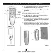
Or, you can mount the remote holder to turn the fan off. 10-5. The reversing switch reverses the direction of the fan. 10-4. Step 10-6 14 42700-01 • 01/15/08 • Hunter Fan Company Step 10-7 Push the light button again to any toggle switch plate with the remote ...plate. You can simply mount the remote holder on and controlling the light and fan speed. 10-2. For best operation, start the fan by pressing high, then select your local battery recycling center for turning the fan off the light. 10-6. 10 • Operating the Remote Control and Mounting ...
Or, you can mount the remote holder to turn the fan off. 10-5. The reversing switch reverses the direction of the fan. 10-4. Step 10-6 14 42700-01 • 01/15/08 • Hunter Fan Company Step 10-7 Push the light button again to any toggle switch plate with the remote ...plate. You can simply mount the remote holder on and controlling the light and fan speed. 10-2. For best operation, start the fan by pressing high, then select your local battery recycling center for turning the fan off the light. 10-6. 10 • Operating the Remote Control and Mounting ...
Owner's Manual
Page 15
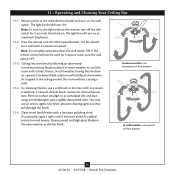
...) will not be used for added protection and beauty. You may use upward air flow pattern 15 42700-01 • 01/15/08 • Hunter Fan Company Occasionally, apply a light coat of furniture polish for 5 days or more, turn on the wall switch. Note: For everyday operation, leave the... dampened cloth. In warm weather, use downward air flow pattern In cold weather, use an artistic agent, but never abrasive cleaning agents as the fan finish. Restore power at the ceiling around the room without the remote, turn on at maximum brightness. 11-2. Press the remote control's HIGH speed...
...) will not be used for added protection and beauty. You may use upward air flow pattern 15 42700-01 • 01/15/08 • Hunter Fan Company Occasionally, apply a light coat of furniture polish for 5 days or more, turn on the wall switch. Note: For everyday operation, leave the... dampened cloth. In warm weather, use downward air flow pattern In cold weather, use an artistic agent, but never abrasive cleaning agents as the fan finish. Restore power at the ceiling around the room without the remote, turn on at maximum brightness. 11-2. Press the remote control's HIGH speed...
Owner's Manual
Page 16
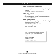
... operation. 1. Be sure that the hanger ball is secure. Turn power off, support fan very carefully, and check that the glass is properly seated. Hunter Fan Company 2500 Frisco Avenue Memphis, Tennessee 38114 16 42700-01 • 01/15/08 • Hunter Fan Company Tighten all the blades. 3. Tighten the blade screws until snug. 2. If...
... operation. 1. Be sure that the hanger ball is secure. Turn power off, support fan very carefully, and check that the glass is properly seated. Hunter Fan Company 2500 Frisco Avenue Memphis, Tennessee 38114 16 42700-01 • 01/15/08 • Hunter Fan Company Tighten all the blades. 3. Tighten the blade screws until snug. 2. If...
Parts Guide
Page 1
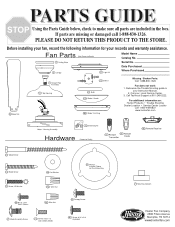
Reference the Trouble Shooting guide in the box. Fan Parts (Not Drawn to make sure all parts are missing or damaged call 1-888-830-1326. Call Technical Support at 901-248-2222. Serial No. Call your Instruction Manual. 2. For additional information on: Hunter Products Trouble Shooting Dealer Location Service Center Locator Call 1-800...
Reference the Trouble Shooting guide in the box. Fan Parts (Not Drawn to make sure all parts are missing or damaged call 1-888-830-1326. Call Technical Support at 901-248-2222. Serial No. Call your Instruction Manual. 2. For additional information on: Hunter Products Trouble Shooting Dealer Location Service Center Locator Call 1-800...


