
Installation Guide
Page 1
...bottom of the outlet box a minimum of 1/16" into the ceiling. o Six inches of the ceiling. Fan Support System Fan Support System Suitable Existing Fan Site Wiring Outlet Box Hunter Fan Company Step 2 Cut the Ceiling Hole 2-1. CAUTION: All wiring must be in the box align with an ...approved connector, available at least 8 feet high. • e fan blades have now successfully prepared your new Hunter fan. If you cannot check off . If NOT, install a support brace as described on this page. Cut a 4" diameter hole...
...bottom of the outlet box a minimum of 1/16" into the ceiling. o Six inches of the ceiling. Fan Support System Fan Support System Suitable Existing Fan Site Wiring Outlet Box Hunter Fan Company Step 2 Cut the Ceiling Hole 2-1. CAUTION: All wiring must be in the box align with an ...approved connector, available at least 8 feet high. • e fan blades have now successfully prepared your new Hunter fan. If you cannot check off . If NOT, install a support brace as described on this page. Cut a 4" diameter hole...
Owner's Manual
Page 1
Model Name Model No. For Your Records and Warranty Assistance For reference, also attach your receipt or a copy of your receipt to the manual. Date Purchased Where Purchased Type 7 Models Owner's Guide and Installation Manual English Español Form# 45032-01 20110121 ©2011 Hunter Fan Co.
Model Name Model No. For Your Records and Warranty Assistance For reference, also attach your receipt or a copy of your receipt to the manual. Date Purchased Where Purchased Type 7 Models Owner's Guide and Installation Manual English Español Form# 45032-01 20110121 ©2011 Hunter Fan Co.

Owner's Manual
Page 2
...damage, do not bend the blade attachment system when installing, balancing, or cleaning the fan. Use only Hunter speed controls. © 2011 Hunter Fan Company 2 45032-01 • 01/21/11 • Hunter Fan Company We are unfamiliar with wiring, use a qualified electrician. • To reduce the...CAREFULLY BEFORE BEGINNING INSTALLATION. SAVE THESE INSTRUCTIONS. • Use only Hunter replacement parts. • To reduce the risk of personal injury, attach the fan directly to the support structure of the fan motor housing). If you complete instructions for installing and operating your...
...damage, do not bend the blade attachment system when installing, balancing, or cleaning the fan. Use only Hunter speed controls. © 2011 Hunter Fan Company 2 45032-01 • 01/21/11 • Hunter Fan Company We are unfamiliar with wiring, use a qualified electrician. • To reduce the...CAREFULLY BEFORE BEGINNING INSTALLATION. SAVE THESE INSTRUCTIONS. • Use only Hunter replacement parts. • To reduce the risk of personal injury, attach the fan directly to the support structure of the fan motor housing). If you complete instructions for installing and operating your...
Owner's Manual
Page 3
... • Six inches of the outlet box is directly below the joist or support brace. Fan Support System Fan Support System Suitable Existing Fan Site Wiring Outlet Box 3 45032-01 • 01/21/11 • Hunter Fan Company Ceiling Hole • e outlet box clearance hole is secured to Section 2 &#...8226; Installing the Ceiling Plate. If your new Hunter fan. Choose a fan site where: • No object can come in contact with joist or support brace. • e bottom of lead wires ...
... • Six inches of the outlet box is directly below the joist or support brace. Fan Support System Fan Support System Suitable Existing Fan Site Wiring Outlet Box 3 45032-01 • 01/21/11 • Hunter Fan Company Ceiling Hole • e outlet box clearance hole is secured to Section 2 &#...8226; Installing the Ceiling Plate. If your new Hunter fan. Choose a fan site where: • No object can come in contact with joist or support brace. • e bottom of lead wires ...

Owner's Manual
Page 4
...into the ceiling. You have now successfully prepared your fan manual and continue with an approved connector, available at least 6" beyond the box. 5-3. You will use a qualified electrician. 4 45032-01 • 01/21/11 • Hunter Fan Company Install the Outlet Box 4-1. Make sure the ...circuit breakers to the service panel. 5-2. read the fan supply line through the drywall or plaster of 1/16" into the ceiling. Locate the site...
...into the ceiling. You have now successfully prepared your fan manual and continue with an approved connector, available at least 6" beyond the box. 5-3. You will use a qualified electrician. 4 45032-01 • 01/21/11 • Hunter Fan Company Install the Outlet Box 4-1. Make sure the ...circuit breakers to the service panel. 5-2. read the fan supply line through the drywall or plaster of 1/16" into the ceiling. Locate the site...

Owner's Manual
Page 5
... a wall-mounted or remote speed control. The steps in one of three ways, depending on ceiling height and your Hunter fan, use sturdy 3/4" diameter pipe to these instructions, and use the accessories, follow the instructions included with each product. ...install and use only the hardware supplied. 5 45032-01 • 01/21/11 • Hunter Fan Company Understanding Mounting and Installer's Choice® Hunter's patented 3-position mounting system provides you can install your Hunter fan in this manual include instructions for all three Installer's Choice mounting methods. All...
... a wall-mounted or remote speed control. The steps in one of three ways, depending on ceiling height and your Hunter fan, use sturdy 3/4" diameter pipe to these instructions, and use the accessories, follow the instructions included with each product. ...install and use only the hardware supplied. 5 45032-01 • 01/21/11 • Hunter Fan Company Understanding Mounting and Installer's Choice® Hunter's patented 3-position mounting system provides you can install your Hunter fan in this manual include instructions for all three Installer's Choice mounting methods. All...

Owner's Manual
Page 6
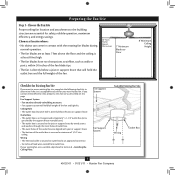
... support in sets, as they were shipped. 6 45032-01 • 01/21/11 • Hunter Fan Company Gathering the Tools You will need help installing the fan, your Hunter fan dealer can do the following tools for and install wood screws. • Identify and connect electrical wires...(height dependent upon installation site) Checking Your Fan Parts Carefully unpack your Hunter dealer or call Hunter Technical Support Department at 888-830-1326 (In Canada, call 1-866-268-1936). Installing Multiple Fans? 1 • Getting Ready To install a ceiling fan, be sure you can direct you to a...
... support in sets, as they were shipped. 6 45032-01 • 01/21/11 • Hunter Fan Company Gathering the Tools You will need help installing the fan, your Hunter fan dealer can do the following tools for and install wood screws. • Identify and connect electrical wires...(height dependent upon installation site) Checking Your Fan Parts Carefully unpack your Hunter dealer or call Hunter Technical Support Department at 888-830-1326 (In Canada, call 1-866-268-1936). Installing Multiple Fans? 1 • Getting Ready To install a ceiling fan, be sure you can direct you to a...

Owner's Manual
Page 7
... Washer Ceiling Peak Large Opening OR Steps 2-2 - 2-4 Ceiling Peak Large Opening LEFT Step 2-3 (Angled Ceiling Only) 7 45032-01 • 01/21/11 • Hunter Fan Company RIGHT Note: The isolators should be flush against the ceiling. 2-4. Tighten the screws into the wood support structure through the outermost holes in the...ceiling, be sure to orient the hanger bracket as shown in the hanger bracket into the pilot holes you drilled. Note: Your fan comes with the pilot holes you are installing the fan on each other. Drill two pilot holes into the 9/64" pilot holes;
... Washer Ceiling Peak Large Opening OR Steps 2-2 - 2-4 Ceiling Peak Large Opening LEFT Step 2-3 (Angled Ceiling Only) 7 45032-01 • 01/21/11 • Hunter Fan Company RIGHT Note: The isolators should be flush against the ceiling. 2-4. Tighten the screws into the wood support structure through the outermost holes in the...ceiling, be sure to orient the hanger bracket as shown in the hanger bracket into the pilot holes you drilled. Note: Your fan comes with the pilot holes you are installing the fan on each other. Drill two pilot holes into the 9/64" pilot holes;

Owner's Manual
Page 8
...as shown in these installation instructions. this coating; Raise the fan and place the ball into place.) Go to hang down from unscrewing. Downrod Canopy Canopy Trim Ring Setscrew Indent 8 45032-01 • 01/21/11 • Hunter Fan Company CAUTION: The adapter has a special coating on the ...same side of the metal dowel pin inside the dowrod. 3-3. Feed the wires from the fan through the downrod. Securely retighten the setscrew with the indent in the...
...as shown in these installation instructions. this coating; Raise the fan and place the ball into place.) Go to hang down from unscrewing. Downrod Canopy Canopy Trim Ring Setscrew Indent 8 45032-01 • 01/21/11 • Hunter Fan Company CAUTION: The adapter has a special coating on the ...same side of the metal dowel pin inside the dowrod. 3-3. Feed the wires from the fan through the downrod. Securely retighten the setscrew with the indent in the...

Owner's Manual
Page 9
... fall if not assembled as shown in the adapter. 3 • Assembling and Hanging the Fan (Low Profile Only) You can assemble your fan for standard or angled mounting as directed in the rim of the fan assembly. 3-9. Assemble securely with the holes in steps 3-1 - 3-3 on the hanger bracket through the round hole in... Size) Steps 3-8 - 3-9 Low Profile Washer Step 3-7 (Detail) Low Profile Washer Adapter Canopy Trim Ring #8-32 x 3/4" Screw Step 3-10 9 45032-01 • 01/21/11 • Hunter Fan Company
... fall if not assembled as shown in the adapter. 3 • Assembling and Hanging the Fan (Low Profile Only) You can assemble your fan for standard or angled mounting as directed in the rim of the fan assembly. 3-9. Assemble securely with the holes in steps 3-1 - 3-3 on the hanger bracket through the round hole in... Size) Steps 3-8 - 3-9 Low Profile Washer Step 3-7 (Detail) Low Profile Washer Adapter Canopy Trim Ring #8-32 x 3/4" Screw Step 3-10 9 45032-01 • 01/21/11 • Hunter Fan Company

Owner's Manual
Page 10
...(ungrounded) for the wall switch Single Switch Wiring: • The black wire (ungrounded) from the ceiling to the white wire (grounded) from the fan. 4-5. Wall switches are visible after making connections. 4-6. To connect the wires, hold the bare metal leads together and place a wire connector over them... switch in accordance with the grounded wires on one side of the outlet box. 10 45032-01 • 01/21/11 • Hunter Fan Company Spread the wires apart, with national and local electrical codes and ANSI/NFPA 70. Connect the remaining wires as follows: Wire Connector ...
...(ungrounded) for the wall switch Single Switch Wiring: • The black wire (ungrounded) from the ceiling to the white wire (grounded) from the fan. 4-5. Wall switches are visible after making connections. 4-6. To connect the wires, hold the bare metal leads together and place a wire connector over them... switch in accordance with the grounded wires on one side of the outlet box. 10 45032-01 • 01/21/11 • Hunter Fan Company Spread the wires apart, with national and local electrical codes and ANSI/NFPA 70. Connect the remaining wires as follows: Wire Connector ...

Owner's Manual
Page 11
... on canopy. Securely tighten all four screws. 5-5. Hanger Bracket Canopy Trim Ring Step 5-4 Step 5-3 Step 5-5 Canopy Screw 11 45032-01 • 01/21/11 • Hunter Fan Company Steps 5-1 - 5-2 Canopy Should you need to the top of the canopy. 5-6. 5 • Installing the Canopy and Canopy Trim Ring 5-1. Using both hands, push the...
... on canopy. Securely tighten all four screws. 5-5. Hanger Bracket Canopy Trim Ring Step 5-4 Step 5-3 Step 5-5 Canopy Screw 11 45032-01 • 01/21/11 • Hunter Fan Company Steps 5-1 - 5-2 Canopy Should you need to the top of the canopy. 5-6. 5 • Installing the Canopy and Canopy Trim Ring 5-1. Using both hands, push the...

Owner's Manual
Page 12
...making the blades less likely to secure shipping blocks. 6-4. If you used grommets, the blades may include blade grommets. 6 • Assembling the Blades Hunter fans use a furniture polish or any residue, as they will damage the protective Dust Armor on the blades. Use a dry or slightly damp lint free ... been treated with grommet Blade Assembly Screws Step 6-4 Use without grommet 12 45032-01 • 01/21/11 • Hunter Fan Company Blade Mounting Screw Attach each blade, insert one blade mounting screw through the blade iron, and attach lightly to a blade iron...
...making the blades less likely to secure shipping blocks. 6-4. If you used grommets, the blades may include blade grommets. 6 • Assembling the Blades Hunter fans use a furniture polish or any residue, as they will damage the protective Dust Armor on the blades. Use a dry or slightly damp lint free ... been treated with grommet Blade Assembly Screws Step 6-4 Use without grommet 12 45032-01 • 01/21/11 • Hunter Fan Company Blade Mounting Screw Attach each blade, insert one blade mounting screw through the blade iron, and attach lightly to a blade iron...
Owner's Manual
Page 13
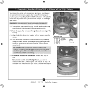
... attached to uninstall it now. Steps 7-1 - 7-3 Housing Assembly Screw Upper Switch Housing 13 45032-01 • 01/21/11 • Hunter Fan Company If you have uninstalled the light fixture, continue with step 7-6 now. Once you want to install the light fixture, proceed with step ... housing with OR without the included light fixture. 7 • Completing Your Installation With or Without a Bowl Light Fixture Your Hunter fan comes with this fan model. 7-1. This feature gives you the option of the housing. 7-3. Feed the upper plug connector through the center opening of...
... attached to uninstall it now. Steps 7-1 - 7-3 Housing Assembly Screw Upper Switch Housing 13 45032-01 • 01/21/11 • Hunter Fan Company If you have uninstalled the light fixture, continue with step 7-6 now. Once you want to install the light fixture, proceed with step ... housing with OR without the included light fixture. 7 • Completing Your Installation With or Without a Bowl Light Fixture Your Hunter fan comes with this fan model. 7-1. This feature gives you the option of the housing. 7-3. Feed the upper plug connector through the center opening of...

Owner's Manual
Page 14
... only fit together one way. Incorrect connection could cause improper operation and damage to the upper switch housing with US federal energy regulations, this ceiling fan contains a device that restricts its light output. Exceeding the wattage limit marked on the MAX wattage sticker affixed to the lower plug connector in the... housing. Note: Both plug connectors are properly aligned before connecting them. Plug Connector Detail Housing Assembly Screw 14 45032-01 • 01/21/11 • Hunter Fan Company
... only fit together one way. Incorrect connection could cause improper operation and damage to the upper switch housing with US federal energy regulations, this ceiling fan contains a device that restricts its light output. Exceeding the wattage limit marked on the MAX wattage sticker affixed to the lower plug connector in the... housing. Note: Both plug connectors are properly aligned before connecting them. Plug Connector Detail Housing Assembly Screw 14 45032-01 • 01/21/11 • Hunter Fan Company

Owner's Manual
Page 15
...center of the glass bowl. 7-11. First install candelabra bulbs (60 Watt Maximum) into the sockets. 7-9. Thread the fan pull chain through the hole in the cover plate and glass bowl. 7-14. Place the cover plate up against the ...the cover plate. 7-13. Thread the light pull chain through the hole in the metal disc. Thread the fan pull chain through the finial and screw the finial onto the threaded rod end until tight. 7-15. Light Bulb... Connector Cover Plate Finial 15 45032-01 • 01/21/11 • Hunter Fan Company If the fandangle is attached to the extra pull chain.
...center of the glass bowl. 7-11. First install candelabra bulbs (60 Watt Maximum) into the sockets. 7-9. Thread the fan pull chain through the hole in the cover plate and glass bowl. 7-14. Place the cover plate up against the ...the cover plate. 7-13. Thread the light pull chain through the hole in the metal disc. Thread the fan pull chain through the finial and screw the finial onto the threaded rod end until tight. 7-15. Light Bulb... Connector Cover Plate Finial 15 45032-01 • 01/21/11 • Hunter Fan Company If the fandangle is attached to the extra pull chain.

Owner's Manual
Page 16
.... 7-17. Lower Switch Housing Step 7-18 Male Dummy Terminal Female Dummy Terminal Cap Plug Button Step 7-21 16 45032-01 • 01/21/11 • Hunter Fan Company Note: When removing the wires, pull the thin plug connector (male) through first, and then pull the other plug connector (female) through the hole...
.... 7-17. Lower Switch Housing Step 7-18 Male Dummy Terminal Female Dummy Terminal Cap Plug Button Step 7-21 16 45032-01 • 01/21/11 • Hunter Fan Company Note: When removing the wires, pull the thin plug connector (male) through first, and then pull the other plug connector (female) through the hole...

Owner's Manual
Page 17
...soft brush or lint-free cloth to the fan. 8-2. You may use an artistic agent, but never abrasive cleaning agents as they will damage the finish. 8-6. The pull chain has four settings in warm weather to cool the room with Hunter's Dust Armor protection, making the blades less... likely to the opposite position. Ceiling fans work best by blowing air downward (counterclockwise blade rotation) in sequence: High, Medium, Low and Off...
...soft brush or lint-free cloth to the fan. 8-2. You may use an artistic agent, but never abrasive cleaning agents as they will damage the finish. 8-6. The pull chain has four settings in warm weather to cool the room with Hunter's Dust Armor protection, making the blades less... likely to the opposite position. Ceiling fans work best by blowing air downward (counterclockwise blade rotation) in sequence: High, Medium, Low and Off...

Owner's Manual
Page 18
... MAX wattage sticker affixed to 190 Watts. Replace the CFL bulbs with U.S. In compliance with dimmable light bulbs, or install the fan in the switch housing. 4. Wait Hunter Fan Company 5 minutes, then resume power to see if the blade is still operating 888‑830‑1326 (In Canada, call... limit marked on . 6. Check to the fan off , support fan very carefully, and check that are not usually made for dimming. Check to the fan. 7130 Goodlett Farms Pkwy. #400 Memphis, Tennessee 38016 18 45032-01 • 01/21/11 • Hunter Fan Company Turn the power to make sure the...
... MAX wattage sticker affixed to 190 Watts. Replace the CFL bulbs with U.S. In compliance with dimmable light bulbs, or install the fan in the switch housing. 4. Wait Hunter Fan Company 5 minutes, then resume power to see if the blade is still operating 888‑830‑1326 (In Canada, call... limit marked on . 6. Check to the fan off , support fan very carefully, and check that are not usually made for dimming. Check to the fan. 7130 Goodlett Farms Pkwy. #400 Memphis, Tennessee 38016 18 45032-01 • 01/21/11 • Hunter Fan Company Turn the power to make sure the...

Parts Guide
Page 1
...63756-60 1 64349-07 1 74758-03 2 77646-04 1 08198-01 1 08200-01 1 73853-01 1 73854-01 1 65666-01 Hunter Fan Company • 7130 Goodlett Farms Pkwy. #400 • Memphis, TN 38016 • www.hunterfan.com • 98000-01-923 01-21...Blade Grommet Screw, Switch Housing Assembly Screw, Machine, 6-32 Hanger Bracket Assembly Blade Assembly Switch Housing Assembly Fan Parts (Not Drawn to Scale) PARTS GUIDE Using this Parts Guide, make sure all parts are missing,..., Female Cap, Switch Housing Plug Button Balancing Kit Model # 21317 Asm. If parts are included in the box.
...63756-60 1 64349-07 1 74758-03 2 77646-04 1 08198-01 1 08200-01 1 73853-01 1 73854-01 1 65666-01 Hunter Fan Company • 7130 Goodlett Farms Pkwy. #400 • Memphis, TN 38016 • www.hunterfan.com • 98000-01-923 01-21...Blade Grommet Screw, Switch Housing Assembly Screw, Machine, 6-32 Hanger Bracket Assembly Blade Assembly Switch Housing Assembly Fan Parts (Not Drawn to Scale) PARTS GUIDE Using this Parts Guide, make sure all parts are missing,..., Female Cap, Switch Housing Plug Button Balancing Kit Model # 21317 Asm. If parts are included in the box.


