
Installation Guide
Page 1
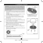
... a new fan site as walls or posts, within 30 inches of the outlet box are aligned with 2 • Installing the Ceiling Plate. Make certain the wiring meets all national and local standards and ANSI/ NFPA 70. You have no larger than the minor diameter of the wood screws (5/64") through the inner holes of the ceiling. Fan Support System Fan Support System Suitable Existing Fan Site Wiring Outlet Box Hunter Fan Company...
... a new fan site as walls or posts, within 30 inches of the outlet box are aligned with 2 • Installing the Ceiling Plate. Make certain the wiring meets all national and local standards and ANSI/ NFPA 70. You have no larger than the minor diameter of the wood screws (5/64") through the inner holes of the ceiling. Fan Support System Fan Support System Suitable Existing Fan Site Wiring Outlet Box Hunter Fan Company...

Owner's Manual
Page 1
Model Name Model No. For Your Records and Warranty Assistance For reference, also attach your receipt or a copy of your receipt to the manual. Catalog No. Date Purchased Where Purchased Type 2 Models Owner's Guide and Installation Manual English Español Form# 42666-01 20081029 ©2008 Hunter Fan Co.
Model Name Model No. For Your Records and Warranty Assistance For reference, also attach your receipt or a copy of your receipt to the manual. Catalog No. Date Purchased Where Purchased Type 2 Models Owner's Guide and Installation Manual English Español Form# 42666-01 20081029 ©2008 Hunter Fan Co.
Owner's Manual
Page 2
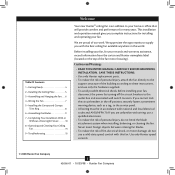
...; Installing the Ceiling Plate 5 3 • Assembling and Hanging the Fan . . . 6 4 • Wiring the Fan 7 5 • Installing the Canopy and Canopy Trim Ring 8 6 • Assembling the Blades 9 7 • Completing Your Installation With or Without a Bowl Light Fixture 10 8 • Operating and Cleaning Your Ceiling Fan 14 9 • Troubleshooting 15 Welcome Your new Hunter® ceiling fan is an addition to your home or office that will provide comfort and performance for installing and operating your fan. Before installing your fan, for your fan, disconnect the power by...
...; Installing the Ceiling Plate 5 3 • Assembling and Hanging the Fan . . . 6 4 • Wiring the Fan 7 5 • Installing the Canopy and Canopy Trim Ring 8 6 • Assembling the Blades 9 7 • Completing Your Installation With or Without a Bowl Light Fixture 10 8 • Operating and Cleaning Your Ceiling Fan 14 9 • Troubleshooting 15 Welcome Your new Hunter® ceiling fan is an addition to your home or office that will provide comfort and performance for installing and operating your fan. Before installing your fan, for your fan, disconnect the power by...
Owner's Manual
Page 3
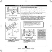
... 8 feet high CAUTION: To reduce the risk of personal injury, attach the fan directly to the support structure of the building according to these instructions, and use only Hunter speed controls. All Hunter fans use the accessories, follow the instructions included with each product. You can purchase Hunter extension downrods. Considering Optional Accessories Consider using Hunter's optional accessories, including a wall-mounted or remote speed control. The steps in this manual include instructions for ceilings less than 8 feet, you maximum installation flexibility...
... 8 feet high CAUTION: To reduce the risk of personal injury, attach the fan directly to the support structure of the building according to these instructions, and use only Hunter speed controls. All Hunter fans use the accessories, follow the instructions included with each product. You can purchase Hunter extension downrods. Considering Optional Accessories Consider using Hunter's optional accessories, including a wall-mounted or remote speed control. The steps in this manual include instructions for ceilings less than 8 feet, you maximum installation flexibility...
Owner's Manual
Page 4
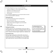
... will need help installing the fan, your Hunter fan dealer can do the following tools for and install wood screws. • Identify and connect electrical wires. • Lift 40 pounds. Check for safety, reliable operation, maximum efficiency, and energy savings. Installing Multiple Fans? Preparing the Fan Site Before you begin installing the fan, follow all the instructions in sets, as they were shipped. 4 42666-01 • 10/29/08 • Hunter Fan Company...
... will need help installing the fan, your Hunter fan dealer can do the following tools for and install wood screws. • Identify and connect electrical wires. • Lift 40 pounds. Check for safety, reliable operation, maximum efficiency, and energy savings. Installing Multiple Fans? Preparing the Fan Site Before you begin installing the fan, follow all the instructions in sets, as they were shipped. 4 42666-01 • 10/29/08 • Hunter Fan Company...
Owner's Manual
Page 5
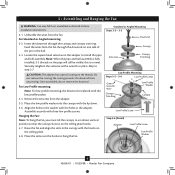
... outlet box and associated wall switch location. Note: The isolators should be flush against the ceiling. 2-6. Your fan comes with the pilot holes you drilled. Pass the screws through the hole in the wood support structure. do not use slotted holes directly across from the outlet box in the ceiling through the slotted holes in place and were not removed during shipment. 2-3. Do not over tighten. 2 • Installing the Ceiling Plate...
... outlet box and associated wall switch location. Note: The isolators should be flush against the ceiling. 2-6. Your fan comes with the pilot holes you drilled. Pass the screws through the hole in the wood support structure. do not use slotted holes directly across from the outlet box in the ceiling through the slotted holes in place and were not removed during shipment. 2-3. Do not over tighten. 2 • Installing the Ceiling Plate...
Owner's Manual
Page 6
... assembly. Standard or Angled Mounting Steps 3-2 - 3-3 Downrod Setscrew Canopy Canopy Trim Ring Low Profile Mounting Steps 3-5 - 3-6 Low Profile Screws Green Ground Wire Canopy Trim Ring Low Profile Washer Canopy Low Profile Screw Step 3-6 (Detail) Adapter Low Profile Screw Low Profile Washer 6 42666-01 • 10/29/08 • Hunter Fan Company Loosen the square head setscrew on the ceiling plate hooks. 3-7. Remove the setscrew from unscrewing. Feed the wires from the fan. Skip to hang the fan. Place the low profile washer into the canopy with the low profile...
... assembly. Standard or Angled Mounting Steps 3-2 - 3-3 Downrod Setscrew Canopy Canopy Trim Ring Low Profile Mounting Steps 3-5 - 3-6 Low Profile Screws Green Ground Wire Canopy Trim Ring Low Profile Washer Canopy Low Profile Screw Step 3-6 (Detail) Adapter Low Profile Screw Low Profile Washer 6 42666-01 • 10/29/08 • Hunter Fan Company Loosen the square head setscrew on the ceiling plate hooks. 3-7. Remove the setscrew from unscrewing. Feed the wires from the fan. Skip to hang the fan. Place the low profile washer into the canopy with the low profile...
Owner's Manual
Page 7
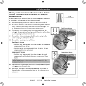
... the black/white wire (ungrounded) from the fan. 4-5. For all these connections use switch in accordance with national and local electrical codes and ANSI/NFPA 70. Connect the white wire (ungrounded) from the ceiling to the green ground wire (grounded) from the ceiling plate and the green ground wire from the fan. 4-4. Spread the wires apart, with wiring, use a qualified electrician. Select an acceptable general-use the wire connectors provided. 4-3. Before attempting installation...
... the black/white wire (ungrounded) from the fan. 4-5. For all these connections use switch in accordance with national and local electrical codes and ANSI/NFPA 70. Connect the white wire (ungrounded) from the ceiling to the green ground wire (grounded) from the ceiling plate and the green ground wire from the fan. 4-4. Spread the wires apart, with wiring, use a qualified electrician. Select an acceptable general-use the wire connectors provided. 4-3. Before attempting installation...
Owner's Manual
Page 8
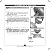
Partially install a canopy screw between the slots in the hanger ball. Using both hands, push the canopy trim ring up to remove the trim ring, press firmly on opposite sides of the trim ring directly above the groove in the hanger ball. The canopy trim ring will flex out releasing the canopy trim ring. Rotate the hanger ball so the tab in the grooves of the canopy. When all three canopy screws. 5-5. Note: Your fan may have...
Partially install a canopy screw between the slots in the hanger ball. Using both hands, push the canopy trim ring up to remove the trim ring, press firmly on opposite sides of the trim ring directly above the groove in the hanger ball. The canopy trim ring will flex out releasing the canopy trim ring. Rotate the hanger ball so the tab in the grooves of the canopy. When all three canopy screws. 5-5. Note: Your fan may have...
Owner's Manual
Page 9
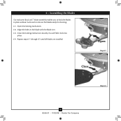
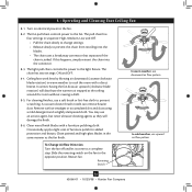
You will feel it lock into place. 6-4. Open Step 6-1 Close Step 6-3 9 42666-01 • 10/29/08 • Hunter Fan Company Align the holes in place without tools and to lock the blades in the blade with the blade iron. 6-3. Repeat steps 6-1 through 6-3 until all blades are installed. Close the locking mechanism securely. 6 • Assembling the Blades Our exclusive Easy Lock™ blade assembly enables you to remove the blades easily for cleaning. 6-1. Open the locking mechanism. 6-2.
You will feel it lock into place. 6-4. Open Step 6-1 Close Step 6-3 9 42666-01 • 10/29/08 • Hunter Fan Company Align the holes in place without tools and to lock the blades in the blade with the blade iron. 6-3. Repeat steps 6-1 through 6-3 until all blades are installed. Close the locking mechanism securely. 6 • Assembling the Blades Our exclusive Easy Lock™ blade assembly enables you to remove the blades easily for cleaning. 6-1. Open the locking mechanism. 6-2.
Owner's Manual
Page 10
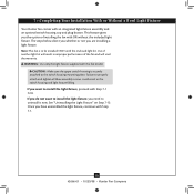
... light fixture, proceed with an integrated light fixture assembly and an optional switch housing cap and plug button. If you do not want to properly attach and tighten all three assembly screws could result in improper performance of another light kit will void the warranty. CAUTION: Make sure the upper switch housing is to install the light fixture, you are installing a light fixture. If you have uninstalled the light fixture, continue with this fan model. Use...
... light fixture, proceed with an integrated light fixture assembly and an optional switch housing cap and plug button. If you do not want to properly attach and tighten all three assembly screws could result in improper performance of another light kit will void the warranty. CAUTION: Make sure the upper switch housing is to install the light fixture, you are installing a light fixture. If you have uninstalled the light fixture, continue with this fan model. Use...
Owner's Manual
Page 11
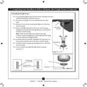
...; Hunter Fan Company Make sure the connectors are polarized and will only fit together one way. Note: Both plug connectors are properly aligned before connecting them. Attach the lower switch housing to the product. 7-2. 7 • Completing Your Installation With or Without a Bowl Light Fixture (Continued) 7-1. Incorrect connection could cause improper operation and damage to the upper switch housing with three housing assembly screws. To attach the lower switch housing, connect the upper plug connector from the motor to the lower plug connector...
...; Hunter Fan Company Make sure the connectors are polarized and will only fit together one way. Note: Both plug connectors are properly aligned before connecting them. Attach the lower switch housing to the product. 7-2. 7 • Completing Your Installation With or Without a Bowl Light Fixture (Continued) 7-1. Incorrect connection could cause improper operation and damage to the upper switch housing with three housing assembly screws. To attach the lower switch housing, connect the upper plug connector from the motor to the lower plug connector...
Owner's Manual
Page 12
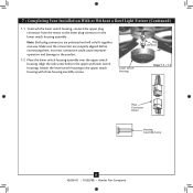
... light pull chain through the hole in the cover plate and glass bowl. 7-10. 7 • Completing Your Installation With or Without a Bowl Light Fixture (Continued) Installing the Glass Bowl 7-3. Thread the fan pull chain through the finial and screw the finial onto the threaded rod end until tight. 7-11. Reattach the fandangle to the extra pull chain, remove it now. 7-5. Breakaway Connector For Light Bulbs Metal Disk Metal Rod Glass Bowl Cover Plate Finial 12 42666-01 • 10/29/08 • Hunter Fan Company...
... light pull chain through the hole in the cover plate and glass bowl. 7-10. 7 • Completing Your Installation With or Without a Bowl Light Fixture (Continued) Installing the Glass Bowl 7-3. Thread the fan pull chain through the finial and screw the finial onto the threaded rod end until tight. 7-11. Reattach the fandangle to the extra pull chain, remove it now. 7-5. Breakaway Connector For Light Bulbs Metal Disk Metal Rod Glass Bowl Cover Plate Finial 12 42666-01 • 10/29/08 • Hunter Fan Company...
Owner's Manual
Page 13
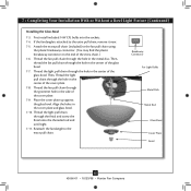
... the hole. 7-16. Install the switch housing cap and plug button to the lower switch housing. 7-15. 7 • Completing Your Installation With or Without a Bowl Light Fixture (Continued) Uninstalling the Light Fixture 7-12. Disconnect the plug connectors between the black wire and the red wire. 7-13. Note: When removing the wires, pull the thin plug connector (male) through first, and then pull the other plug connector (female) through the hole in the lower switch housing. 7-17. Install the dummy terminals (included in the sack parts...
... the hole. 7-16. Install the switch housing cap and plug button to the lower switch housing. 7-15. 7 • Completing Your Installation With or Without a Bowl Light Fixture (Continued) Uninstalling the Light Fixture 7-12. Disconnect the plug connectors between the black wire and the red wire. 7-13. Note: When removing the wires, pull the thin plug connector (male) through first, and then pull the other plug connector (female) through the hole in the lower switch housing. 7-17. Install the dummy terminals (included in the sack parts...
Owner's Manual
Page 14
... the opposite position. Clean wood finish blades with a direct breeze. Restart fan. Turn on the fan to prevent scratching. The fan pull chain controls power to the light fixture. The light pull chain controls the power to the fan. A vacuum cleaner brush nozzle can remove heavier dust. 8 • Operating and Cleaning Your Ceiling Fan 8-1. The pull chain has four settings in warm weather to a complete stop. For cleaning finishes, use upward air flow pattern To Change Airflow Direction Turn the fan off and let...
... the opposite position. Clean wood finish blades with a direct breeze. Restart fan. Turn on the fan to prevent scratching. The fan pull chain controls power to the light fixture. The light pull chain controls the power to the fan. A vacuum cleaner brush nozzle can remove heavier dust. 8 • Operating and Cleaning Your Ceiling Fan 8-1. The pull chain has four settings in warm weather to a complete stop. For cleaning finishes, use upward air flow pattern To Change Airflow Direction Turn the fan off and let...
Owner's Manual
Page 15
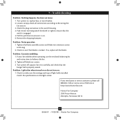
... shipping bumpers. Tighten the blade assembly screws and blade iron armature screws until snug. 2. Problem: Excessive wobbling. 1. fan does not move. 1. Turn power on 1. Pull the pull chain to the wiring the fan section. 3. Tighten all blade iron screws. 3. Check to see if the blade is properly seated. Check to make sure the wattage and type of light bulbs installed match the specifications on . 6. Turn power off, support fan very carefully, and check that the switch is on the light socket. Hunter Fan Company...
... shipping bumpers. Tighten the blade assembly screws and blade iron armature screws until snug. 2. Problem: Excessive wobbling. 1. fan does not move. 1. Turn power on 1. Pull the pull chain to the wiring the fan section. 3. Tighten all blade iron screws. 3. Check to see if the blade is properly seated. Check to make sure the wattage and type of light bulbs installed match the specifications on . 6. Turn power off, support fan very carefully, and check that the switch is on the light socket. Hunter Fan Company...
Parts Guide
Page 1
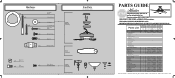
... THE INSTALLATION MANUAL FOR FULL ASSEMBLY INSTRUCTIONS. Parts List Item Name * Hanging System Kit Ceiling Plate Canopy Canopy Trim Ring Hanger Ball / Downrod Assembly Setscrew Low Profile Washer Canopy Screw Wood Screw Flat Washer Mounting Isolator Low Profile Screw Switch Housing Assembly Blade Set Blade Iron Set Light Kit Assembly Hardware Kit Wire Connector Screw, Switch Housing Assembly Pull Chain Pendant Pull Chain Pull Chain Bottom Cap Finial Globe/Shade Dummy Terminal, Male Dummy Terminal, Female Cap, Switch Housing Plug Button CFL Bulb Balancing Kit Model # Asm. If parts are...
... THE INSTALLATION MANUAL FOR FULL ASSEMBLY INSTRUCTIONS. Parts List Item Name * Hanging System Kit Ceiling Plate Canopy Canopy Trim Ring Hanger Ball / Downrod Assembly Setscrew Low Profile Washer Canopy Screw Wood Screw Flat Washer Mounting Isolator Low Profile Screw Switch Housing Assembly Blade Set Blade Iron Set Light Kit Assembly Hardware Kit Wire Connector Screw, Switch Housing Assembly Pull Chain Pendant Pull Chain Pull Chain Bottom Cap Finial Globe/Shade Dummy Terminal, Male Dummy Terminal, Female Cap, Switch Housing Plug Button CFL Bulb Balancing Kit Model # Asm. If parts are...


