
Installation Guide
Page 1
... approved connector, available at any hardware store or electrical supply house. 4-2. For instructions to install your ceiling fan, go to your fan manual and begin with 2 • Installing the Ceiling Plate. Fan Support System o Fan attaches directly to the support brace or joist with the rotating fan blades during normal operation. • e fan blades are at least 7 feet above the ceiling hole. Cut a 4" diameter hole through the outlet box so that will use an existing fan site...
... approved connector, available at any hardware store or electrical supply house. 4-2. For instructions to install your ceiling fan, go to your fan manual and begin with 2 • Installing the Ceiling Plate. Fan Support System o Fan attaches directly to the support brace or joist with the rotating fan blades during normal operation. • e fan blades are at least 7 feet above the ceiling hole. Cut a 4" diameter hole through the outlet box so that will use an existing fan site...
Owner's Manual
Page 1
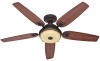
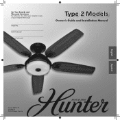
Date Purchased Where Purchased Type 2 Models Owner's Guide and Installation Manual English Español Form# 45057-01 20090624 ©2009 Hunter Fan Co. For Your Records and Warranty Assistance For reference, also attach your receipt or a copy of your receipt to the manual. Model No.
Date Purchased Where Purchased Type 2 Models Owner's Guide and Installation Manual English Español Form# 45057-01 20090624 ©2009 Hunter Fan Co. For Your Records and Warranty Assistance For reference, also attach your receipt or a copy of your receipt to the manual. Model No.
Owner's Manual
Page 2
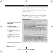
... risk of the fan motor housing). If you complete instructions for your fan. Table Of Contents 1 • Getting Ready 4 2 • Installing the Ceiling Plate 5 3 • Assembling and Hanging the Fan . . . . 6 4 • Wiring the Fan 7 5 • Installing the Canopy and Canopy Trim Ring 8 6 • Assembling the Blades 9 7 • Completing Your Installation With a Light Fixture 10 8 • Operating and Cleaning Your Ceiling Fan 13 9 • Troubleshooting 14 Welcome Your new Hunter® ceiling fan is an addition to the service panel. • All wiring must be...
... risk of the fan motor housing). If you complete instructions for your fan. Table Of Contents 1 • Getting Ready 4 2 • Installing the Ceiling Plate 5 3 • Assembling and Hanging the Fan . . . . 6 4 • Wiring the Fan 7 5 • Installing the Canopy and Canopy Trim Ring 8 6 • Assembling the Blades 9 7 • Completing Your Installation With a Light Fixture 10 8 • Operating and Cleaning Your Ceiling Fan 13 9 • Troubleshooting 14 Welcome Your new Hunter® ceiling fan is an addition to the service panel. • All wiring must be...
Owner's Manual
Page 3
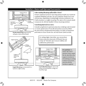
... purchase Hunter extension downrods. Considering Optional Accessories Consider using Hunter's optional accessories, including a wall-mounted or remote speed control. All Hunter fans use the accessories, follow the instructions included with each product. Installer's Choice and Optional Accessories Support Brace Standard Mounting Style Ceiling Outlet Box Standard Mounting hangs from the ceiling by a downrod (included). Angled Mounting Style 8 12 Angled Mounting recommended for a vaulted or angled ceiling Support Brace Low Profile Mounting Style Ceiling Outlet Box Low Profile...
... purchase Hunter extension downrods. Considering Optional Accessories Consider using Hunter's optional accessories, including a wall-mounted or remote speed control. All Hunter fans use the accessories, follow the instructions included with each product. Installer's Choice and Optional Accessories Support Brace Standard Mounting Style Ceiling Outlet Box Standard Mounting hangs from the ceiling by a downrod (included). Angled Mounting Style 8 12 Angled Mounting recommended for a vaulted or angled ceiling Support Brace Low Profile Mounting Style Ceiling Outlet Box Low Profile...
Owner's Manual
Page 4
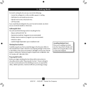
... savings. Proper ceiling fan location and attachment to the motor or fan blades. If you are missing or damaged, contact your Hunter fan dealer can do the following tools for and install wood screws. • Identify and connect electrical wires. • Lift 40 pounds. Refer to the fan parts. Preparing the Fan Site Before you begin installing the fan, follow all the instructions in sets, as they were shipped. 4 45057-01...
... savings. Proper ceiling fan location and attachment to the motor or fan blades. If you are missing or damaged, contact your Hunter fan dealer can do the following tools for and install wood screws. • Identify and connect electrical wires. • Lift 40 pounds. Refer to the fan parts. Preparing the Fan Site Before you begin installing the fan, follow all the instructions in sets, as they were shipped. 4 45057-01...
Owner's Manual
Page 5
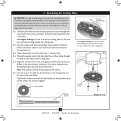
... slotted holes in the ceiling plate with four preinstalled noise isolators. do not use slotted holes directly across from the outlet box in the ceiling through the outermost holes in the wood support structure. If you cannot lock the circuit breakers in place and were not removed during shipment. 2-3. The pilot holes should be 9/64" in the center of the two 3" wood screws. 2-4. Your fan comes...
... slotted holes in the ceiling plate with four preinstalled noise isolators. do not use slotted holes directly across from the outlet box in the ceiling through the outermost holes in the wood support structure. If you cannot lock the circuit breakers in place and were not removed during shipment. 2-3. The pilot holes should be 9/64" in the center of the two 3" wood screws. 2-4. Your fan comes...
Owner's Manual
Page 6
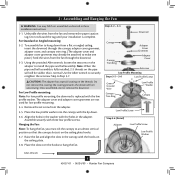
... and Hanging the Fan WARNING: Fan may already be visible; For Low Profile mounting: Note: For low profile mounting, the downrod is complete. Place the slots over the hooks to install the pipe and ball assembly. Steps 3-2 - 3-3 Downrod Canopy Canopy Trim Ring Adapter Cover Grommet Adapter Cover Setscrew Low Profile Mounting Steps 3-5 - 3-6 Low Profile Screws Green Ground Wire Canopy Trim Ring Low Profile Washer Canopy Low Profile Screw Step 3-6 (Detail) Adapter Low Profile Screw Low Profile Washer Allen Wrench 6 45057-01 • 06/24/09 • Hunter Fan Company
... and Hanging the Fan WARNING: Fan may already be visible; For Low Profile mounting: Note: For low profile mounting, the downrod is complete. Place the slots over the hooks to install the pipe and ball assembly. Steps 3-2 - 3-3 Downrod Canopy Canopy Trim Ring Adapter Cover Grommet Adapter Cover Setscrew Low Profile Mounting Steps 3-5 - 3-6 Low Profile Screws Green Ground Wire Canopy Trim Ring Low Profile Washer Canopy Low Profile Screw Step 3-6 (Detail) Adapter Low Profile Screw Low Profile Washer Allen Wrench 6 45057-01 • 06/24/09 • Hunter Fan Company
Owner's Manual
Page 7
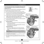
... outlet box. 7 45057-01 • 06/24/09 • Hunter Fan Company fsdfsdf Wire Connector Dual Switch Wiring Single Switch Wiring Connect the remaining wires as follows: Dual Switch Wiring: • The black wire (ungrounded) from the ceiling to the black wire (ungrounded) from the fan • The black/white wire (ungrounded) from the fan to the wire (ungrounded) for the wall switch Single Switch Wiring: • The black wire (ungrounded) from the ceiling to the black (ungrounded) and the black/white wire (ungrounded) from the fan. 4-5. Wall switches...
... outlet box. 7 45057-01 • 06/24/09 • Hunter Fan Company fsdfsdf Wire Connector Dual Switch Wiring Single Switch Wiring Connect the remaining wires as follows: Dual Switch Wiring: • The black wire (ungrounded) from the ceiling to the black wire (ungrounded) from the fan • The black/white wire (ungrounded) from the fan to the wire (ungrounded) for the wall switch Single Switch Wiring: • The black wire (ungrounded) from the ceiling to the black (ungrounded) and the black/white wire (ungrounded) from the fan. 4-5. Wall switches...
Owner's Manual
Page 8
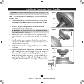
... install two canopy screws into place. Partially install a canopy screw into the hole between the two ceiling plate tabs.When all three canopy screws. 5-5. Using both hands, push the canopy trim ring up with the mounting holes on the trim ring opposite the grooves in the grooves of the canopy. WARNING: The slots in the hanger ball groove. Step 5-1 Tab Groove Step 5-2 Step 5-3 Canopy Canopy Trim Ring Canopy Screw 8 45057-01 • 06/24/09 • Hunter Fan Company Note...
... install two canopy screws into place. Partially install a canopy screw into the hole between the two ceiling plate tabs.When all three canopy screws. 5-5. Using both hands, push the canopy trim ring up with the mounting holes on the trim ring opposite the grooves in the grooves of the canopy. WARNING: The slots in the hanger ball groove. Step 5-1 Tab Groove Step 5-2 Step 5-3 Canopy Canopy Trim Ring Canopy Screw 8 45057-01 • 06/24/09 • Hunter Fan Company Note...
Owner's Manual
Page 9
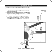
... both mounting screws. Remove the blade mounting screws and rubber shipping bumpers from the motor. Blade Assembly Screw Blade Washer Blade Mounting Screw 9 45057-01 • 06/24/09 • Hunter Fan Company Steps 6-1 - 6-3 Note: Some blade mounting screws are installed in the motor to the fan. 6 • Assembling the Blades Hunter fans use several styles of fan blade irons (brackets that hold the blade to a blade iron using three blade washers and three blade assembly screws. 6-2. Attach each blade, insert one blade mounting screw through the blade iron, and attach lightly to...
... both mounting screws. Remove the blade mounting screws and rubber shipping bumpers from the motor. Blade Assembly Screw Blade Washer Blade Mounting Screw 9 45057-01 • 06/24/09 • Hunter Fan Company Steps 6-1 - 6-3 Note: Some blade mounting screws are installed in the motor to the fan. 6 • Assembling the Blades Hunter fans use several styles of fan blade irons (brackets that hold the blade to a blade iron using three blade washers and three blade assembly screws. 6-2. Attach each blade, insert one blade mounting screw through the blade iron, and attach lightly to...

Owner's Manual
Page 10
... Housing CAUTION: Make sure the light kit top housing is securely attached to properly attach and tighten all three screws firmly. Failure to the light kit mounting plate. 7 • Completing Your Installation With a Light Fixture Your Hunter fan comes with this fan model. 7-1. WARNING: Use only the light fixture supplied with an integrated light fixture assembly. Light Kit Mounting Plate 7-4. Upper Plug Connector Steps 7-1 - 7-3 Housing Assembly Screw 10 45057-01 • 06/24/09 • Hunter Fan Company Install the remaining screw into the light kit mounting plate...
... Housing CAUTION: Make sure the light kit top housing is securely attached to properly attach and tighten all three screws firmly. Failure to the light kit mounting plate. 7 • Completing Your Installation With a Light Fixture Your Hunter fan comes with this fan model. 7-1. WARNING: Use only the light fixture supplied with an integrated light fixture assembly. Light Kit Mounting Plate 7-4. Upper Plug Connector Steps 7-1 - 7-3 Housing Assembly Screw 10 45057-01 • 06/24/09 • Hunter Fan Company Install the remaining screw into the light kit mounting plate...

Owner's Manual
Page 11
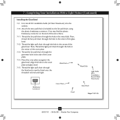
...one way. To attach the light kit, connect the upper plug connector from the motor to the product. 7-6. Partially install two housing assembly screws into the housing. Housing Assembly Screw Light Kit Housing Assembly Screw Light Kit Top Housing Steps 7-5 Plug Connector Detail Keyhole Slots Light Kit Steps 7-6-7-8 Note: In compliance with the housing assembly screws. 7-8. Note: Both plug connectors are firmly situated in fire hazard or improper operation. 11 45057-01 • 06/24/09 • Hunter Fan Company 7 • Completing Your Installation With a Light Fixture (Continued...
...one way. To attach the light kit, connect the upper plug connector from the motor to the product. 7-6. Partially install two housing assembly screws into the housing. Housing Assembly Screw Light Kit Housing Assembly Screw Light Kit Top Housing Steps 7-5 Plug Connector Detail Keyhole Slots Light Kit Steps 7-6-7-8 Note: In compliance with the housing assembly screws. 7-8. Note: Both plug connectors are firmly situated in fire hazard or improper operation. 11 45057-01 • 06/24/09 • Hunter Fan Company 7 • Completing Your Installation With a Light Fixture (Continued...
Owner's Manual
Page 12
... the light pull chain through the grommet hole in the center of the extra chain.) 7-11. Breakaway Connector Cover Plate Finial Metal Disk Light Bulbs (B10 Candelabra Base 40 Watt Maximum) Glass Bowl Steps 7-9-7-15 12 45057-01 • 06/24/09 • Hunter Fan Company Thread the light pull chain through the hole in the center of the glass bowl. Place the cover plate up against the glass bowl. Then, Thread the light pull chain throught the hole in the...
... the light pull chain through the grommet hole in the center of the extra chain.) 7-11. Breakaway Connector Cover Plate Finial Metal Disk Light Bulbs (B10 Candelabra Base 40 Watt Maximum) Glass Bowl Steps 7-9-7-15 12 45057-01 • 06/24/09 • Hunter Fan Company Thread the light pull chain through the hole in the center of the glass bowl. Place the cover plate up against the glass bowl. Then, Thread the light pull chain throught the hole in the...
Owner's Manual
Page 13
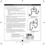
... fan. 8 • Operating and Cleaning Your Ceiling Fan 8-1. If this happens, simply reinsert the chain into the blades. • The chain uses a breakaway connector that separates if the chain is jerked. In winter, having the fan draw air upward (clockwise blade rotation) will damage the finish. 8-6. Clean wood finish blades with a direct breeze. The light pull chain controls the power to prevent scratching. The chain has two settings: ON and OFF. 8-4. For cleaning finishes, use upward air flow...
... fan. 8 • Operating and Cleaning Your Ceiling Fan 8-1. If this happens, simply reinsert the chain into the blades. • The chain uses a breakaway connector that separates if the chain is jerked. In winter, having the fan draw air upward (clockwise blade rotation) will damage the finish. 8-6. Clean wood finish blades with a direct breeze. The light pull chain controls the power to prevent scratching. The chain has two settings: ON and OFF. 8-4. For cleaning finishes, use upward air flow...
Owner's Manual
Page 14
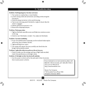
Turn power on 1. Problem: Noisy operation. 1. Check to balance the fan. 2. Turn the power to make sure the wattage and type of light bulbs installed match the specifications on . 6. Tighten the blade assembly screws and blade iron armature screws until snug. 2. If your fan wobbles when operating, use the enclosed balancing kit and instructions to see if the blade is properly seated. If you need parts or service assistance, please call 888‑830‑1326 (In...
Turn power on 1. Problem: Noisy operation. 1. Check to balance the fan. 2. Turn the power to make sure the wattage and type of light bulbs installed match the specifications on . 6. Tighten the blade assembly screws and blade iron armature screws until snug. 2. If your fan wobbles when operating, use the enclosed balancing kit and instructions to see if the blade is properly seated. If you need parts or service assistance, please call 888‑830‑1326 (In...
Parts Guide
Page 1
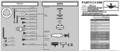
.... Parts List Item # Item Name 1 * Hanging System Kit 2 Ceiling Plate 3 Canopy 4 Canopy Trim Ring 7 Hanger Ball / Downrod Assembly 8 Setscrew 27 Low Profile Washer 62 Canopy Screw 64 Wood Screw 65 Wood Screw 68 Flat Washer 71 Mounting Isolator 100 * Screw, Low Profile 168 Light Kit Top Housing 49 Light Kit Assembly 44 Blade Iron Set 46 Blade Set 47 Screw, Blade Iron Armature 150 Globe/Shade 148 Bottom Cap 149 Finial 60 Hardware Kit 196 Washer, Blade 67 Blade Assembly Screw 69 Screw, Machine, 6-32 70 Wire Connector 75 Balancing Kit 76 Pull Chain...
.... Parts List Item # Item Name 1 * Hanging System Kit 2 Ceiling Plate 3 Canopy 4 Canopy Trim Ring 7 Hanger Ball / Downrod Assembly 8 Setscrew 27 Low Profile Washer 62 Canopy Screw 64 Wood Screw 65 Wood Screw 68 Flat Washer 71 Mounting Isolator 100 * Screw, Low Profile 168 Light Kit Top Housing 49 Light Kit Assembly 44 Blade Iron Set 46 Blade Set 47 Screw, Blade Iron Armature 150 Globe/Shade 148 Bottom Cap 149 Finial 60 Hardware Kit 196 Washer, Blade 67 Blade Assembly Screw 69 Screw, Machine, 6-32 70 Wire Connector 75 Balancing Kit 76 Pull Chain...


