
Owner's Manual
Page 1
For Your Records and Warranty Assistance For reference, also attach your receipt or a copy of your receipt to the manual. Model Name Model No. Date Purchased Where Purchased Type 2 Models Owner's Guide and Installation Manual English Español Form# 45028-01 20110215 ©2011 Hunter Fan Co.
For Your Records and Warranty Assistance For reference, also attach your receipt or a copy of your receipt to the manual. Model Name Model No. Date Purchased Where Purchased Type 2 Models Owner's Guide and Installation Manual English Español Form# 45028-01 20110215 ©2011 Hunter Fan Co.
Owner's Manual
Page 2
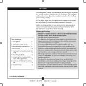
... local electrical codes and ANSI/NFPA 70. Use only Hunter speed controls. © 2010 Hunter Fan Company 2 45028-01 • 02/15/11 • Hunter Fan Company Welcome Table Of Contents 1 • Getting Ready 6 2 • Installing the Hanger Bracket 7 3 • Assembling and Hanging the Fan . . . . 8 4 •Wiring the Fan 10 5 • Installing the Canopy and Canopy Trim Ring 11 6 • Assembling the Blades 12 7 • Completing Your Installation With a Multi Staked Light Fixture 13 8 • Operating and Cleaning Your Ceiling Fan 15 9 • Troubleshooting 16...
... local electrical codes and ANSI/NFPA 70. Use only Hunter speed controls. © 2010 Hunter Fan Company 2 45028-01 • 02/15/11 • Hunter Fan Company Welcome Table Of Contents 1 • Getting Ready 6 2 • Installing the Hanger Bracket 7 3 • Assembling and Hanging the Fan . . . . 8 4 •Wiring the Fan 10 5 • Installing the Canopy and Canopy Trim Ring 11 6 • Assembling the Blades 12 7 • Completing Your Installation With a Multi Staked Light Fixture 13 8 • Operating and Cleaning Your Ceiling Fan 15 9 • Troubleshooting 16...
Owner's Manual
Page 3
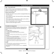
... every item, prepare a new fan site as walls or posts, within 30 inches of the fan blade tips. • The fan is directly below the joist or support brace. Fan Support System Fan Support System Suitable Existing Fan Site Wiring Outlet Box 3 45028-01 • 02/15/11 • Hunter Fan Company Fan Support System • Fan attaches directly to building structure. • Fan support system will hold full weight of the outlet box is acceptable and...
... every item, prepare a new fan site as walls or posts, within 30 inches of the fan blade tips. • The fan is directly below the joist or support brace. Fan Support System Fan Support System Suitable Existing Fan Site Wiring Outlet Box 3 45028-01 • 02/15/11 • Hunter Fan Company Fan Support System • Fan attaches directly to building structure. • Fan support system will hold full weight of the outlet box is acceptable and...
Owner's Manual
Page 4
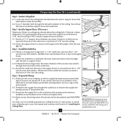
... now successfully prepared your fan manual and continue with two #8 x 1-1/2" Step 4 wood screws and washers. For instructions to install your ceiling fan, go to the fan supply line leads and associated wall switch location are unfamiliar with the joist or support brace. 4-3. Step 5 CAUTION: All wiring must be in the box align with wiring, use the hole to ensure it is a ceiling joist directly above the ceiling hole. If you cannot lock...
... now successfully prepared your fan manual and continue with two #8 x 1-1/2" Step 4 wood screws and washers. For instructions to install your ceiling fan, go to the fan supply line leads and associated wall switch location are unfamiliar with the joist or support brace. 4-3. Step 5 CAUTION: All wiring must be in the box align with wiring, use the hole to ensure it is a ceiling joist directly above the ceiling hole. If you cannot lock...
Owner's Manual
Page 5
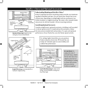
...can purchase Hunter extension downrods. Considering Optional Accessories Consider using Hunter's optional accessories, including a wall-mounted or remote speed control. Support Brace Ceiling Outlet Box For ceilings higher than 8 feet high CAUTION: To reduce the risk of personal injury, attach the fan directly to the support structure of your preference: Low Profile, Standard, or Angled mounting. Angled Mounting Style 8 12 Angled Mounting recommended for a vaulted or angled ceiling Support Brace Low Profile Mounting Style Ceiling Outlet Box Low Profile Mounting fits close...
...can purchase Hunter extension downrods. Considering Optional Accessories Consider using Hunter's optional accessories, including a wall-mounted or remote speed control. Support Brace Ceiling Outlet Box For ceilings higher than 8 feet high CAUTION: To reduce the risk of personal injury, attach the fan directly to the support structure of your preference: Low Profile, Standard, or Angled mounting. Angled Mounting Style 8 12 Angled Mounting recommended for a vaulted or angled ceiling Support Brace Low Profile Mounting Style Ceiling Outlet Box Low Profile Mounting fits close...
Owner's Manual
Page 6
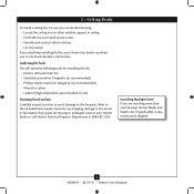
... • 02/15/11 • Hunter Fan Company If any shipping damage to the included Parts Guide. Installing Multiple Fans? If you are missing or damaged, contact your fan to avoid damage to a licensed installer or electrician. Gathering the Tools You will need help installing the fan, your Hunter fan dealer can do the following tools for and install wood screws. • Identify and connect electrical wires. • Lift 40 pounds.
... • 02/15/11 • Hunter Fan Company If any shipping damage to the included Parts Guide. Installing Multiple Fans? If you are missing or damaged, contact your fan to avoid damage to a licensed installer or electrician. Gathering the Tools You will need help installing the fan, your Hunter fan dealer can do the following tools for and install wood screws. • Identify and connect electrical wires. • Lift 40 pounds.
Owner's Manual
Page 7
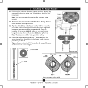
... noise isolators. Do not over tighten. 3" Screw Flat Washer Ceiling Peak Large Opening OR Steps 2-2 - 2-4 Ceiling Peak Large Opening LEFT Step 2-3 (Angled Ceiling Only) 7 45028-01 • 02/15/11 • Hunter Fan Company RIGHT Drill two pilot holes into the wood support structure through the outermost holes in the wood support structure. Note: Your fan comes with the pilot holes you drilled in the outlet box. Isolator Hanger Bracket...
... noise isolators. Do not over tighten. 3" Screw Flat Washer Ceiling Peak Large Opening OR Steps 2-2 - 2-4 Ceiling Peak Large Opening LEFT Step 2-3 (Angled Ceiling Only) 7 45028-01 • 02/15/11 • Hunter Fan Company RIGHT Drill two pilot holes into the wood support structure through the outermost holes in the wood support structure. Note: Your fan comes with the pilot holes you drilled in the outlet box. Isolator Hanger Bracket...
Owner's Manual
Page 8
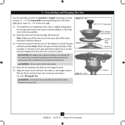
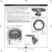
... assemble fan to 4 • Wiring the Fan. Feed the wires from unscrewing. Securely retighten the setscrew with Washer) Canopy Trim Ring Setscrew Indent 8 45028-01 • 02/15/11 • Hunter Fan Company the coating prevents the downrod from the fan through the downrod. Align the notch on the ball with the indent in the hanger bracket. (Rotate the fan until you hear the notch pop into the hanger bracket...
... assemble fan to 4 • Wiring the Fan. Feed the wires from unscrewing. Securely retighten the setscrew with Washer) Canopy Trim Ring Setscrew Indent 8 45028-01 • 02/15/11 • Hunter Fan Company the coating prevents the downrod from the fan through the downrod. Align the notch on the ball with the indent in the hanger bracket. (Rotate the fan until you hear the notch pop into the hanger bracket...
Owner's Manual
Page 9
... the hanger bracket through the round hole in the rim of the fan assembly. 3-9. Raise the fan and place the hook on this page. 3-6. Place the canopy trim ring and canopy with washer on the previous page. Remove the screws from the parts sack into the canopy. 3-8. 3 • Assembling and Hanging the Fan (Low Profile Only) You can assemble your fan for standard or angled mounting as directed in these installation instructions. Align the screw holes in the washer...
... the hanger bracket through the round hole in the rim of the fan assembly. 3-9. Raise the fan and place the hook on this page. 3-6. Place the canopy trim ring and canopy with washer on the previous page. Remove the screws from the parts sack into the canopy. 3-8. 3 • Assembling and Hanging the Fan (Low Profile Only) You can assemble your fan for standard or angled mounting as directed in these installation instructions. Align the screw holes in the washer...
Owner's Manual
Page 10
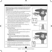
... with wiring, use switch in accordance with the grounded wires on one side of the outlet box and the ungrounded wires on the low profile washer. 4-4. Turn the wire connectors upward and push them , then twist clockwise until tight. Connect the white wire (ungrounded) from the ceiling to the black (ungrounded) and the black/white wire (ungrounded) from the fan can be in accordance with national and local electrical codes. 4-1. Wall switches...
... with wiring, use switch in accordance with the grounded wires on one side of the outlet box and the ungrounded wires on the low profile washer. 4-4. Turn the wire connectors upward and push them , then twist clockwise until tight. Connect the white wire (ungrounded) from the ceiling to the black (ungrounded) and the black/white wire (ungrounded) from the fan can be in accordance with national and local electrical codes. 4-1. Wall switches...
Owner's Manual
Page 11
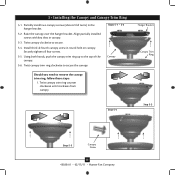
... clockwise until it releases from canopy. Partially install two canopy screws (about 2 full turns) in canopy. 5-3. Raise the canopy over the hanger bracket. Steps 5-1 - 5-2 Canopy Should you need to secure. 5-4. Hanger Bracket Canopy Trim Ring Step 5-4 Step 5-3 Step 5-5 Canopy Screw 11 45028-01 • 02/15/11 • Hunter Fan Company Align partially installed screws with key slots in the hanger bracket. 5-2. Securely tighten all four screws. 5-5. Install third & fourth canopy screw in round hole on canopy. 5 • Installing the Canopy and Canopy Trim Ring 5-1.
... clockwise until it releases from canopy. Partially install two canopy screws (about 2 full turns) in canopy. 5-3. Raise the canopy over the hanger bracket. Steps 5-1 - 5-2 Canopy Should you need to secure. 5-4. Hanger Bracket Canopy Trim Ring Step 5-4 Step 5-3 Step 5-5 Canopy Screw 11 45028-01 • 02/15/11 • Hunter Fan Company Align partially installed screws with key slots in the hanger bracket. 5-2. Securely tighten all four screws. 5-5. Install third & fourth canopy screw in round hole on canopy. 5 • Installing the Canopy and Canopy Trim Ring 5-1.
Owner's Manual
Page 12
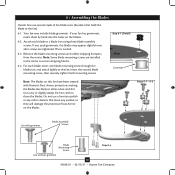
... installed in the motor to clean the blades. For each blade to the fan). 6-1. Do not use several styles of fan blade irons (brackets that leave any other cleaners that hold the blade to a blade iron using three blade assembly screws. Note: Some blade mounting screws are tightened. Insert the second blade mounting screw, then securely tighten both mounting screws. This is normal. 6-3. Step 6-1 (Detail) Grommet Note: The blades on the blades. 6-2. If you used grommets, the blades may include blade grommets. Remove the blade mounting screws and rubber shipping bumpers...
... installed in the motor to clean the blades. For each blade to the fan). 6-1. Do not use several styles of fan blade irons (brackets that leave any other cleaners that hold the blade to a blade iron using three blade assembly screws. Note: Some blade mounting screws are tightened. Insert the second blade mounting screw, then securely tighten both mounting screws. This is normal. 6-3. Step 6-1 (Detail) Grommet Note: The blades on the blades. 6-2. If you used grommets, the blades may include blade grommets. Remove the blade mounting screws and rubber shipping bumpers...
Owner's Manual
Page 13
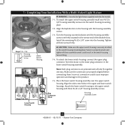
... the housing assembly screws are polarized and will only fit together one way. Note: Both plug connectors are firmly situated in the switch housing fixture falling. 7-4. Incorrect connection could result in the narrow end of the keyhole slots. Align the side screw holes in the lower switch housing assembly. 7 • Completing Your Installation With a Multi Staked Light Fixture WARNING: Use only the light fixture supplied with the housing assembly screws. 7-3. Install the remaining #6-32 x 3/8" screw into the switch housing mounting plate...
... the housing assembly screws are polarized and will only fit together one way. Note: Both plug connectors are firmly situated in the switch housing fixture falling. 7-4. Incorrect connection could result in the narrow end of the keyhole slots. Align the side screw holes in the lower switch housing assembly. 7 • Completing Your Installation With a Multi Staked Light Fixture WARNING: Use only the light fixture supplied with the housing assembly screws. 7-3. Install the remaining #6-32 x 3/8" screw into the switch housing mounting plate...
Owner's Manual
Page 14
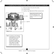
..., this ceiling fan contains a device that restricts its light output. Remove the plastic from the silhouette on the MAX wattage sticker affixed to the light socket(s) may result in fire hazard or improper operation. 14 45028-01 • 02/15/11 • Hunter Fan Company Shade Remove the protective wrap from each ). Exceeding the wattage limit marked on the motor housing before starting the fan. Install four Type B light bulbs (40...
..., this ceiling fan contains a device that restricts its light output. Remove the plastic from the silhouette on the MAX wattage sticker affixed to the light socket(s) may result in fire hazard or improper operation. 14 45028-01 • 02/15/11 • Hunter Fan Company Shade Remove the protective wrap from each ). Exceeding the wattage limit marked on the motor housing before starting the fan. Install four Type B light bulbs (40...
Owner's Manual
Page 15
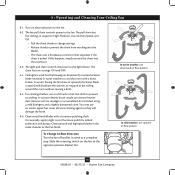
... • Hunter Fan Company The fan pull chain controls power to the light fixture. To Change Airflow Direction Turn the fan off and let it come to prevent the chain from recoiling into the connector. 8-3. Reversing Switch In warm weather, use downward air flow pattern In cold weather, use a soft brush or lint-free cloth to the opposite position. Clean wood finish blades with a direct breeze. Restart fan. The pull chain has five settings in sequence: High, Medium, Low, Serenity Speed, and...
... • Hunter Fan Company The fan pull chain controls power to the light fixture. To Change Airflow Direction Turn the fan off and let it come to prevent the chain from recoiling into the connector. 8-3. Reversing Switch In warm weather, use downward air flow pattern In cold weather, use a soft brush or lint-free cloth to the opposite position. Clean wood finish blades with a direct breeze. Restart fan. The pull chain has five settings in sequence: High, Medium, Low, Serenity Speed, and...
Owner's Manual
Page 16
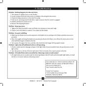
... switch is properly seated. Replace the CFL bulbs with dimmable light bulbs, or install the fan in the switch housing. 4. Push motor reversing switch firmly left or right to the blade assembly instructions provided. 2. Problem: Noisy operation 1. Problem: Lights shut off at http://www.hunterfan.com. Turn the power to see if the blade is still operating 1. Problem: CFL bulbs flicker when controlled by a dimming remote or wall control 1. Loosen canopy, check all the blades. Tighten the blade assembly screws and blade iron armature screws until snug. 2. Hunter Fan Company...
... switch is properly seated. Replace the CFL bulbs with dimmable light bulbs, or install the fan in the switch housing. 4. Push motor reversing switch firmly left or right to the blade assembly instructions provided. 2. Problem: Noisy operation 1. Problem: Lights shut off at http://www.hunterfan.com. Turn the power to see if the blade is still operating 1. Problem: CFL bulbs flicker when controlled by a dimming remote or wall control 1. Loosen canopy, check all the blades. Tighten the blade assembly screws and blade iron armature screws until snug. 2. Hunter Fan Company...
Parts Guide
Page 1
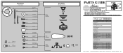
... Ceiling Plate Canopy Canopy Trim Ring Hanger Ball / Downrod Assembly Setscrew Low Profile Washer Canopy Screw Wood Screw Wood Screw Flat Washer Mounting Isolator * Locking Screw Switch Housing Assembly Blade Iron Set Blade Set Screw, Blade Iron Armature Hardware Kit Blade Grommet Blade Assembly Screw Screw, Machine, 6-32 Wire Connector Screw, Switch Housing Assembly Balancing Kit Pull Chain Pendant Pull Chain Pendant Pull Chain Pull Chain Light bulb / Bulb Globe/Shade Model # 20715 Asm. THIS PARTS GUIDE IS FOR REFERENCE ONLY. REFER TO THE INSTALLATION MANUAL FOR FULL ASSEMBLY INSTRUCTIONS...
... Ceiling Plate Canopy Canopy Trim Ring Hanger Ball / Downrod Assembly Setscrew Low Profile Washer Canopy Screw Wood Screw Wood Screw Flat Washer Mounting Isolator * Locking Screw Switch Housing Assembly Blade Iron Set Blade Set Screw, Blade Iron Armature Hardware Kit Blade Grommet Blade Assembly Screw Screw, Machine, 6-32 Wire Connector Screw, Switch Housing Assembly Balancing Kit Pull Chain Pendant Pull Chain Pendant Pull Chain Pull Chain Light bulb / Bulb Globe/Shade Model # 20715 Asm. THIS PARTS GUIDE IS FOR REFERENCE ONLY. REFER TO THE INSTALLATION MANUAL FOR FULL ASSEMBLY INSTRUCTIONS...


