
Installation Guide
Page 1
... connector, available at least 6" beyond the box. 5-3. Outlet Box o e outlet box is secured to outlet box by an approved connector. Wiring o e electrical cable is an UL-approved octagonal 4" x 1-1/2" outlet box (or as walls or posts, within 30 inches of outlet box. Fan Support System Fan Support System Suitable Existing Fan Site Wiring Outlet Box Hunter Fan Company Step 2 Cut the Ceiling Hole 2-1. Cut a 4" diameter hole through the inner holes of the fan and light kit. If NOT, install a support...
... connector, available at least 6" beyond the box. 5-3. Outlet Box o e outlet box is secured to outlet box by an approved connector. Wiring o e electrical cable is an UL-approved octagonal 4" x 1-1/2" outlet box (or as walls or posts, within 30 inches of outlet box. Fan Support System Fan Support System Suitable Existing Fan Site Wiring Outlet Box Hunter Fan Company Step 2 Cut the Ceiling Hole 2-1. Cut a 4" diameter hole through the inner holes of the fan and light kit. If NOT, install a support...

Owner's Manual
Page 1
Model Name Model No. Date Purchased Where Purchased Type T Models Owner's Guide and Installation Manual English Español Form# 42452-01 20110114 ©2011 Hunter Fan Co. For Your Records and Warranty Assistance For reference, also attach your receipt or a copy of your receipt to the manual.
Model Name Model No. Date Purchased Where Purchased Type T Models Owner's Guide and Installation Manual English Español Form# 42452-01 20110114 ©2011 Hunter Fan Co. For Your Records and Warranty Assistance For reference, also attach your receipt or a copy of your receipt to the manual.
Owner's Manual
Page 2
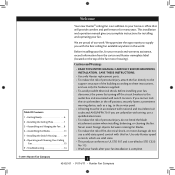
... instructions, and use a solid-state speed control with national and local electrical codes and ANSI/NFPA 70. This installation and operation manual gives you cannot lock the circuit breakers in the off the circuit breakers to the support structure of the fan motor housing). Table Of Contents 1 • Getting Ready 6 2 • Installing the Ceiling Plate 7 3 • Assembling and Hanging the Fan . . . 8 6 • Assembling the Blades 11 7 • Installing the Switch Housing 12 8 • Operating and Cleaning...
... instructions, and use a solid-state speed control with national and local electrical codes and ANSI/NFPA 70. This installation and operation manual gives you cannot lock the circuit breakers in the off the circuit breakers to the support structure of the fan motor housing). Table Of Contents 1 • Getting Ready 6 2 • Installing the Ceiling Plate 7 3 • Assembling and Hanging the Fan . . . 8 6 • Assembling the Blades 11 7 • Installing the Switch Housing 12 8 • Operating and Cleaning...
Owner's Manual
Page 3
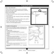
... full weight of the fan and light kit. If your new Hunter fan. If you want to use an existing fan site, complete the following checklist to outlet box by wood screws and washers through the inner holes of outlet box. • The outer holes of lead wires extend from outlet box. Fan Support System Fan Support System Suitable Existing Fan Site Wiring Outlet Box 3 42452-01 • 01/14/11 • Hunter Fan Company Wiring • The electrical...
... full weight of the fan and light kit. If your new Hunter fan. If you want to use an existing fan site, complete the following checklist to outlet box by wood screws and washers through the inner holes of outlet box. • The outer holes of lead wires extend from outlet box. Fan Support System Fan Support System Suitable Existing Fan Site Wiring Outlet Box 3 42452-01 • 01/14/11 • Hunter Fan Company Wiring • The electrical...
Owner's Manual
Page 4
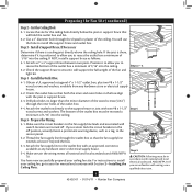
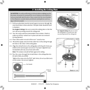
... is a ceiling joist directly above the ceiling hole. Install the Outlet Box 4-1. You will hold the outlet box and fan. 2-2. Obtain a UL-approved octagonal 4" x 1-1/2" outlet box, plus two #8 x 1-1/2" wood screws and washers, available from any hardware store or electrical supply house. 5-4. Step 3 - Steps 2 - 3 3-2. Orient the outlet box so that will use a qualified electrician. 4 42452-01 • 01/14/11 • Hunter Fan Company Step 5 CAUTION: All wiring must be...
... is a ceiling joist directly above the ceiling hole. Install the Outlet Box 4-1. You will hold the outlet box and fan. 2-2. Obtain a UL-approved octagonal 4" x 1-1/2" outlet box, plus two #8 x 1-1/2" wood screws and washers, available from any hardware store or electrical supply house. 5-4. Step 3 - Steps 2 - 3 3-2. Orient the outlet box so that will use a qualified electrician. 4 42452-01 • 01/14/11 • Hunter Fan Company Step 5 CAUTION: All wiring must be...
Owner's Manual
Page 5
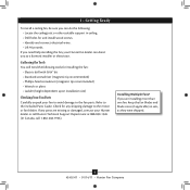
... 3-position mounting system provides you can install your Hunter fan in this manual include instructions for ceilings less than 8 feet, you maximum installation flexibility and ease. To install and use only Hunter speed controls. Considering Optional Accessories Consider using Hunter's optional accessories, including a wall-mounted or remote speed control. For quiet and optimum performance of three ways, depending on ceiling height and your Hunter fan, use the accessories, follow the instructions included with each product. You can purchase Hunter extension downrods.
... 3-position mounting system provides you can install your Hunter fan in this manual include instructions for ceilings less than 8 feet, you maximum installation flexibility and ease. To install and use only Hunter speed controls. Considering Optional Accessories Consider using Hunter's optional accessories, including a wall-mounted or remote speed control. For quiet and optimum performance of three ways, depending on ceiling height and your Hunter fan, use the accessories, follow the instructions included with each product. You can purchase Hunter extension downrods.
Owner's Manual
Page 6
... the motor or fan blades. Installing Multiple Fans? If any shipping damage to the included Parts Guide. Check for any parts are installing more than one fan, keep the fan blades and blade irons (if applicable) in ceiling. • Drill holes for and install wood screws. • Identify and connect electrical wires. • Lift 40 pounds. Gathering the Tools You will need help installing the fan, your Hunter fan dealer can do the following tools for installing the fan: • Electric...
... the motor or fan blades. Installing Multiple Fans? If any shipping damage to the included Parts Guide. Check for any parts are installing more than one fan, keep the fan blades and blade irons (if applicable) in ceiling. • Drill holes for and install wood screws. • Identify and connect electrical wires. • Lift 40 pounds. Gathering the Tools You will need help installing the fan, your Hunter fan dealer can do the following tools for installing the fan: • Electric...
Owner's Manual
Page 7
... wires from each of the ceiling plate. 2-5. Pass the screws through the hole in the center of the two 3" wood screws. 2-4. Align the slotted holes in the ceiling plate with four preinstalled noise isolators. Drill two pilot holes into the 9/64" pilot holes; Tighten the screws into the wood support structure through the outermost holes in the outlet box. 2 • Installing the Ceiling Plate CAUTION: To avoid possible electrical shock, before installing...
... wires from each of the ceiling plate. 2-5. Pass the screws through the hole in the center of the two 3" wood screws. 2-4. Align the slotted holes in the ceiling plate with four preinstalled noise isolators. Drill two pilot holes into the 9/64" pilot holes; Tighten the screws into the wood support structure through the outermost holes in the outlet box. 2 • Installing the Ceiling Plate CAUTION: To avoid possible electrical shock, before installing...
Owner's Manual
Page 8
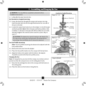
... holes in the washer with the holes in the ball. 3-3. Securely retighten the setscrew with the low profile washer. 3-4. the coating prevents the downrod from the fan. Remove the setscrew from the fan through the canopy and canopy trim ring. Standard or Angled Mounting Steps 3-2 - 3-3 Downrod Setscrew Canopy Canopy Trim Ring Low Profile Mounting Steps 3-5 - 3-6 Low Profile Screws Green Ground Wire Canopy Trim Ring Low Profile Washer Canopy Low Profile Screw Step 3-6 (Detail) Adapter Low Profile Screw Low Profile Washer 8 42452-01 • 01/14/11 • Hunter Fan Company...
... holes in the washer with the holes in the ball. 3-3. Securely retighten the setscrew with the low profile washer. 3-4. the coating prevents the downrod from the fan. Remove the setscrew from the fan through the canopy and canopy trim ring. Standard or Angled Mounting Steps 3-2 - 3-3 Downrod Setscrew Canopy Canopy Trim Ring Low Profile Mounting Steps 3-5 - 3-6 Low Profile Screws Green Ground Wire Canopy Trim Ring Low Profile Washer Canopy Low Profile Screw Step 3-6 (Detail) Adapter Low Profile Screw Low Profile Washer 8 42452-01 • 01/14/11 • Hunter Fan Company...
Owner's Manual
Page 9
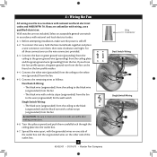
... black wire (ungrounded) from the ceiling to the green ground wire (grounding) from the ceiling plate and the green ground wire (grounding) from the fan. 4-5. 4 • Wiring the Fan All wiring must be found on the other side of the outlet box. 9 42452-01 • 01/14/11 • Hunter Fan Company Wire Connector Dual Switch Wiring Single Switch Wiring Before attempting installation, make sure the power is still off. 4-2. Wall switches are visible after making connections...
... black wire (ungrounded) from the ceiling to the green ground wire (grounding) from the ceiling plate and the green ground wire (grounding) from the fan. 4-5. 4 • Wiring the Fan All wiring must be found on the other side of the outlet box. 9 42452-01 • 01/14/11 • Hunter Fan Company Wire Connector Dual Switch Wiring Single Switch Wiring Before attempting installation, make sure the power is still off. 4-2. Wall switches are visible after making connections...
Owner's Manual
Page 10
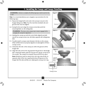
... in the canopy is recommended you need to remove the trim ring, press firmly on opposite sides of the trim ring directly above the groove in the canopy. When all three canopy screws. 5-5. Using both hands, push the canopy trim ring up with the mounting holes on the trim ring opposite the grooves in the hanger ball. Step 5-1 Tab Groove Step 5-2 Step 5-3 Canopy Canopy Trim Ring Canopy Screw 10 42452-01 • 01/14/11 • Hunter Fan Company
... in the canopy is recommended you need to remove the trim ring, press firmly on opposite sides of the trim ring directly above the groove in the canopy. When all three canopy screws. 5-5. Using both hands, push the canopy trim ring up with the mounting holes on the trim ring opposite the grooves in the hanger ball. Step 5-1 Tab Groove Step 5-2 Step 5-3 Canopy Canopy Trim Ring Canopy Screw 10 42452-01 • 01/14/11 • Hunter Fan Company
Owner's Manual
Page 11
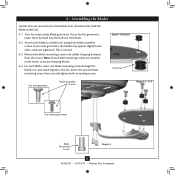
... each blade to the fan. If your fan has grommets, insert them by hand into the holes on the blades. 6-2. Attach each blade, insert one blade mounting screw through the blade iron, and attach lightly to a blade iron using three blade assembly screws. Your fan may appear slightly loose after screws are installed in the motor to the fan). 6-1. 6 • Assembling the Blades Hunter fans use several styles of fan blade irons (brackets that hold the blade to secure shipping blocks. 6-4. Remove the blade mounting screws and rubber shipping bumpers from the motor.
... each blade to the fan. If your fan has grommets, insert them by hand into the holes on the blades. 6-2. Attach each blade, insert one blade mounting screw through the blade iron, and attach lightly to a blade iron using three blade assembly screws. Your fan may appear slightly loose after screws are installed in the motor to the fan). 6-1. 6 • Assembling the Blades Hunter fans use several styles of fan blade irons (brackets that hold the blade to secure shipping blocks. 6-4. Remove the blade mounting screws and rubber shipping bumpers from the motor.
Owner's Manual
Page 12
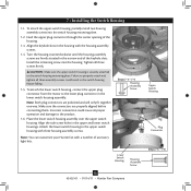
... in the switch housing fixture falling. 7-5. Attach the lower switch housing to the lower plug connector in the upper and lower switch housings. Feed the upper plug connector through the center opening of accessory light kits. Align the side screw holes in the lower switch housing assembly. Steps 7-1 - 7-4 Housing Assembly Screw Lower Switch Housing Housing Assembly Screw 12 42452-01 • 01/14/11 • Hunter Fan Company Upper Switch Housing Plug Connector Steps 7-5 - 7-6 To attach the upper switch housing, partially install two housing assembly screws into...
... in the switch housing fixture falling. 7-5. Attach the lower switch housing to the lower plug connector in the upper and lower switch housings. Feed the upper plug connector through the center opening of accessory light kits. Align the side screw holes in the lower switch housing assembly. Steps 7-1 - 7-4 Housing Assembly Screw Lower Switch Housing Housing Assembly Screw 12 42452-01 • 01/14/11 • Hunter Fan Company Upper Switch Housing Plug Connector Steps 7-5 - 7-6 To attach the upper switch housing, partially install two housing assembly screws into...
Owner's Manual
Page 13
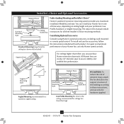
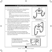
... fan. Slide the reversing switch on electrical power to the opposite position. Occasionally, apply a light coat of furniture polish for added protection and beauty. In warm weather, use downward air flow pattern In cold weather, use a soft brush or lint-free cloth to a complete stop. A vacuum cleaner brush nozzle can remove heavier dust. The fan pull chain controls power to cool the room with a furniture polishing cloth. Ceiling fans work best...
... fan. Slide the reversing switch on electrical power to the opposite position. Occasionally, apply a light coat of furniture polish for added protection and beauty. In warm weather, use downward air flow pattern In cold weather, use a soft brush or lint-free cloth to a complete stop. A vacuum cleaner brush nozzle can remove heavier dust. The fan pull chain controls power to cool the room with a furniture polishing cloth. Ceiling fans work best...
Owner's Manual
Page 14
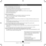
... the specifications on , replace fuse, or reset breaker. 2. Check the plug connection in the switch housing. 4. Turn the power to make sure the wattage and type of the light bulbs that the hanger ball is still operating 1. Check to the blade assembly instructions provided. 2. Make sure the blades are securely attached to balance the fan. 3. Wait 5 minutes, then resume power to the wiring the fan section. 3. Turn power on the light socket. 2. Remove the shipping bumpers. 9 • Troubleshooting Problem...
... the specifications on , replace fuse, or reset breaker. 2. Check the plug connection in the switch housing. 4. Turn the power to make sure the wattage and type of the light bulbs that the hanger ball is still operating 1. Check to the blade assembly instructions provided. 2. Make sure the blades are securely attached to balance the fan. 3. Wait 5 minutes, then resume power to the wiring the fan section. 3. Turn power on the light socket. 2. Remove the shipping bumpers. 9 • Troubleshooting Problem...
Owner's Manual
Page 15
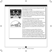
... at low speed settings. With this ENERGY STAR qualified Hunter ceiling fan! Every degree you set by purchasing this purchase, you can cut air pollution by a Hunter ceiling fan lets you raise the thermostat saves up to 10%* on ENERGY STAR visit www.energystar.gov. 15 42452-01 • 01/14/11 • Hunter Fan Company Hunter fans have more efficient fan motors and air delivery due to more aerodynamic blade configurations...
... at low speed settings. With this ENERGY STAR qualified Hunter ceiling fan! Every degree you set by purchasing this purchase, you can cut air pollution by a Hunter ceiling fan lets you raise the thermostat saves up to 10%* on ENERGY STAR visit www.energystar.gov. 15 42452-01 • 01/14/11 • Hunter Fan Company Hunter fans have more efficient fan motors and air delivery due to more aerodynamic blade configurations...
Parts Guide
Page 1
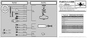
...; www.hunterfan.com • 98000-01-577 01-14-2011 • ©2011 Part List Item Name * Hanging System Kit Ceiling Plate Canopy Canopy Trim Ring Hanger Ball / Downrod Assembly Low Profile Washer Screw, Wood Screw, Wood Flat Washer Isolator Locking Screw Canopy Screw Set Screw Switch/Housing Assembly Blade Iron Set Blade Set Blade Iron Armature Screw * Hardware Kit Rubber Blade Grommet Blade Assembly Screw Screw, Machine, 6-32 Wire Connector Screw, Switch Housing Assembly Balancing Kit Model # Asm. REFER TO THE INSTALLATION MANUAL FOR FULL ASSEMBLY INSTRUCTIONS. THIS PARTS GUIDE IS...
...; www.hunterfan.com • 98000-01-577 01-14-2011 • ©2011 Part List Item Name * Hanging System Kit Ceiling Plate Canopy Canopy Trim Ring Hanger Ball / Downrod Assembly Low Profile Washer Screw, Wood Screw, Wood Flat Washer Isolator Locking Screw Canopy Screw Set Screw Switch/Housing Assembly Blade Iron Set Blade Set Blade Iron Armature Screw * Hardware Kit Rubber Blade Grommet Blade Assembly Screw Screw, Machine, 6-32 Wire Connector Screw, Switch Housing Assembly Balancing Kit Model # Asm. REFER TO THE INSTALLATION MANUAL FOR FULL ASSEMBLY INSTRUCTIONS. THIS PARTS GUIDE IS...


