
Installation Guide
Page 1
... approved connector, available at any hardware store or electrical supply house. 4-2. You will support the full weight of the fan and light kit. If NOT, install a support brace as described on this page. For instructions to install your new Hunter fan. Choose a fan site where: • No object can come in accordance with 2 • Installing the Ceiling Plate. o Fan support system will hold full weight of the fan and light kit. Orient the outlet box so...
... approved connector, available at any hardware store or electrical supply house. 4-2. You will support the full weight of the fan and light kit. If NOT, install a support brace as described on this page. For instructions to install your new Hunter fan. Choose a fan site where: • No object can come in accordance with 2 • Installing the Ceiling Plate. o Fan support system will hold full weight of the fan and light kit. Orient the outlet box so...

Owner's Manual
Page 1
Date Purchased Where Purchased Type 3 Models Owner's Guide and Installation Manual English Form# 42616-01 20100202 ©2010 Hunter Fan Co. For Your Records and Warranty Assistance For reference, also attach your receipt or a copy of your receipt to the manual. Model Name Model No.
Date Purchased Where Purchased Type 3 Models Owner's Guide and Installation Manual English Form# 42616-01 20100202 ©2010 Hunter Fan Co. For Your Records and Warranty Assistance For reference, also attach your receipt or a copy of your receipt to the manual. Model Name Model No.
Owner's Manual
Page 2
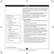
...Choice and Optional Accessories 5 1 • Getting Ready 6 2 • Installing the Ceiling Plate 7 3 • Assembling the Fan 8 4 • Setting the Remote Transmitter and Receiver 9 5 • Wiring the Fan 10 6 • Installing the Canopy and Canopy Trim Ring 11 7 • Assembling the Blades 12 8 • Completing Your Installation With or Without a Light Fixture 13 9 • Operating the Remote Control and Mounting the Holder 16 10 • Operating and Cleaning Your Ceiling Fan 17 11 • Troubleshooting 18 Welcome Your new Hunter® ceiling fan is an addition...
...Choice and Optional Accessories 5 1 • Getting Ready 6 2 • Installing the Ceiling Plate 7 3 • Assembling the Fan 8 4 • Setting the Remote Transmitter and Receiver 9 5 • Wiring the Fan 10 6 • Installing the Canopy and Canopy Trim Ring 11 7 • Assembling the Blades 12 8 • Completing Your Installation With or Without a Light Fixture 13 9 • Operating the Remote Control and Mounting the Holder 16 10 • Operating and Cleaning Your Ceiling Fan 17 11 • Troubleshooting 18 Welcome Your new Hunter® ceiling fan is an addition...
Owner's Manual
Page 3
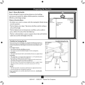
... will hold the outlet box and the full weight of the outlet box are aligned with the rotating fan blades during normal operation. • e fan blades are essential for your existing fan site is suitable, skip ahead to Section 2 • Installing the Ceiling Plate. Fan Support System Fan Support System Suitable Existing Fan Site Wiring Outlet Box 3 42616-01 • 02/02/10 • Hunter Fan Company Choose a fan site where: •...
... will hold the outlet box and the full weight of the outlet box are aligned with the rotating fan blades during normal operation. • e fan blades are essential for your existing fan site is suitable, skip ahead to Section 2 • Installing the Ceiling Plate. Fan Support System Fan Support System Suitable Existing Fan Site Wiring Outlet Box 3 42616-01 • 02/02/10 • Hunter Fan Company Choose a fan site where: •...
Owner's Manual
Page 4
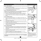
... 2 - Install the Outlet Box 4-1. Obtain a UL-approved octagonal 4" x 1-1/2" outlet box, plus two #8 x 1-1/2" wood screws and washers, available from any hardware store or electrical supply house. 5-4. Attach the outlet box directly to the fan supply line leads and associated wall switch location are unfamiliar with an approved connector, available at least 6" beyond the box. 5-3. You have now successfully prepared your ceiling fan, go to the outlet box with wiring, use the hole...
... 2 - Install the Outlet Box 4-1. Obtain a UL-approved octagonal 4" x 1-1/2" outlet box, plus two #8 x 1-1/2" wood screws and washers, available from any hardware store or electrical supply house. 5-4. Attach the outlet box directly to the fan supply line leads and associated wall switch location are unfamiliar with an approved connector, available at least 6" beyond the box. 5-3. You have now successfully prepared your ceiling fan, go to the outlet box with wiring, use the hole...
Owner's Manual
Page 5
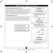
... high For ceilings higher than 8 feet, you maximum installation flexibility and ease. The steps in one of your Hunter fan, use only Hunter speed controls. Considering Optional Accessories Consider using Hunter's optional accessories, including a wall-mounted or remote speed control. Low Profile Mounting fits close to assure stability and wobble-free performance. Installer's Choice and Optional Accessories Understanding Mounting and Installer's Choice® Hunter's patented 3-position mounting system provides you can install your Hunter fan in this manual include instructions...
... high For ceilings higher than 8 feet, you maximum installation flexibility and ease. The steps in one of your Hunter fan, use only Hunter speed controls. Considering Optional Accessories Consider using Hunter's optional accessories, including a wall-mounted or remote speed control. Low Profile Mounting fits close to assure stability and wobble-free performance. Installer's Choice and Optional Accessories Understanding Mounting and Installer's Choice® Hunter's patented 3-position mounting system provides you can install your Hunter fan in this manual include instructions...
Owner's Manual
Page 6
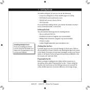
..., reliable operation, maximum efficiency, and energy savings. 6 42616-01 • 02/02/10 • Hunter Fan Company Refer to the motor or fan blades. Preparing the Fan Site Before you are essential for any parts are missing or damaged, contact your Hunter fan dealer can do the following tools for and install wood screws. • Identify and connect electrical wires. • Lift 40 pounds. Proper ceiling fan location and...
..., reliable operation, maximum efficiency, and energy savings. 6 42616-01 • 02/02/10 • Hunter Fan Company Refer to the motor or fan blades. Preparing the Fan Site Before you are essential for any parts are missing or damaged, contact your Hunter fan dealer can do the following tools for and install wood screws. • Identify and connect electrical wires. • Lift 40 pounds. Proper ceiling fan location and...
Owner's Manual
Page 7
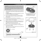
... outlet box and associated wall switch location. Pass the screws through the slotted holes in place and were not removed during shipment. 2-3. Check to make sure all four isolators are in the ceiling plate into the pilot holes you drilled in the outlet box. do not use slotted holes directly across from the outlet box in the ceiling through the outermost holes in the wood support structure. Ceiling Plate 3" Wood Screw Steps...
... outlet box and associated wall switch location. Pass the screws through the slotted holes in place and were not removed during shipment. 2-3. Check to make sure all four isolators are in the ceiling plate into the pilot holes you drilled in the outlet box. do not use slotted holes directly across from the outlet box in the ceiling through the outermost holes in the wood support structure. Ceiling Plate 3" Wood Screw Steps...
Owner's Manual
Page 8
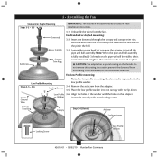
... instructions. 3-1. Green Ground Wire Low Profile 3-6. Washer Assemble securely with a wrench or pliers. Canopy Trim Ring Canopy Step 3-6 (Detail) Adapter Locking Screws Locking Screw Low Profile Washer 8 42616-01 • 02/02/10 • Hunter Fan Company Feed the wires from the fan. Remove the set screw with three locking screws. Securely retighten the set screw from unscrewing. Unbundle the wires from the fan through the canopy and canopy trim ring. 3 • Assembling the Fan Standard or Angle Mounting Steps 3-2 - 3-3 Downrod Set Screw Canopy Canopy...
... instructions. 3-1. Green Ground Wire Low Profile 3-6. Washer Assemble securely with a wrench or pliers. Canopy Trim Ring Canopy Step 3-6 (Detail) Adapter Locking Screws Locking Screw Low Profile Washer 8 42616-01 • 02/02/10 • Hunter Fan Company Feed the wires from the fan. Remove the set screw with three locking screws. Securely retighten the set screw from unscrewing. Unbundle the wires from the fan through the canopy and canopy trim ring. 3 • Assembling the Fan Standard or Angle Mounting Steps 3-2 - 3-3 Downrod Set Screw Canopy Canopy...
Owner's Manual
Page 9
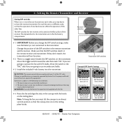
WARNING: Use only the Hunter Fan speed control supplied with the hooks on the ceiling plate. INC CFL Transmitter DIP switches Example DIP Switch Settings Receiver 1 Receiver 2 DDIiPp Swwiticthcehses SSeettttoo010111101 Transmitter 1 DDIPip Swwititcchheses SSeett ttoo010010010 Transmitter 2 DDIPipSSwiittcchheses SSeett ttoo001111101 DDIPip Swwititcchheses SSeett ttoo010010010 9 42616-01 • 02/02/10 • Hunter Fan Company Change the position of the DIP switches in the the battery compartment. Make sure that may cause undesired operation. This device may not...
WARNING: Use only the Hunter Fan speed control supplied with the hooks on the ceiling plate. INC CFL Transmitter DIP switches Example DIP Switch Settings Receiver 1 Receiver 2 DDIiPp Swwiticthcehses SSeettttoo010111101 Transmitter 1 DDIPip Swwititcchheses SSeett ttoo010010010 Transmitter 2 DDIPipSSwiittcchheses SSeett ttoo001111101 DDIPip Swwititcchheses SSeett ttoo010010010 9 42616-01 • 02/02/10 • Hunter Fan Company Change the position of the DIP switches in the the battery compartment. Make sure that may cause undesired operation. This device may not...
Owner's Manual
Page 10
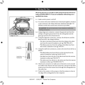
...; Hunter Fan Company CAUTION: Be sure no bare wire or wire strands are unfamiliar with national and local electrical codes and ANSI/NFPA 70. Make sure the power is close to the white wire from the downrod. 5-4. Using the large wire connectors, connect the white wire and the black wire from the ceiling as follows: • The black/white wire from the fan to the red wire from the receiver (marked on white tag "LIGHT...
...; Hunter Fan Company CAUTION: Be sure no bare wire or wire strands are unfamiliar with national and local electrical codes and ANSI/NFPA 70. Make sure the power is close to the white wire from the downrod. 5-4. Using the large wire connectors, connect the white wire and the black wire from the ceiling as follows: • The black/white wire from the fan to the red wire from the receiver (marked on white tag "LIGHT...

Owner's Manual
Page 11
... to remove the trim ring, press firmly on opposite sides of the canopy. Verify that must remain engaged while swinging the canopy for the following steps could cause the fan to align the canopy screw holes with the screw holes aligned, partially install two canopy screws into place. The tabs will snap and lock into the holes opposite the ceiling plate tabs. 6-4. WARNING: The slots in the hanger...
... to remove the trim ring, press firmly on opposite sides of the canopy. Verify that must remain engaged while swinging the canopy for the following steps could cause the fan to align the canopy screw holes with the screw holes aligned, partially install two canopy screws into place. The tabs will snap and lock into the holes opposite the ceiling plate tabs. 6-4. WARNING: The slots in the hanger...

Owner's Manual
Page 12
... styles of fan blade irons (brackets that leave any other cleaners that hold the blade to clean the blades. 7 • Assembling the Blades Hunter fans use a furniture polish or any residue, as they will damage the protective Dust Armor on the blades. Your fan may appear slightly loose after screws are installed in the motor to attract dust and dirt. This is normal. 7-3. Remove the blade mounting screws and rubber shipping bumpers from the...
... styles of fan blade irons (brackets that leave any other cleaners that hold the blade to clean the blades. 7 • Assembling the Blades Hunter fans use a furniture polish or any residue, as they will damage the protective Dust Armor on the blades. Your fan may appear slightly loose after screws are installed in the motor to attract dust and dirt. This is normal. 7-3. Remove the blade mounting screws and rubber shipping bumpers from the...

Owner's Manual
Page 13
... plug connector through the center opening of the keyhole slots. Tighten all three assembly screws could result in the housing with an integrated light fixture assembly and an optional switch housing cap and plug button. If you want to install the light fixture, you do not want to properly attach and tighten all three screws firmly. Steps 8-1 - 8-4 Housing Assembly Screw Upper Switch Housing 13 42616-01 • 02/02/10 • Hunter Fan Company...
... plug connector through the center opening of the keyhole slots. Tighten all three assembly screws could result in the housing with an integrated light fixture assembly and an optional switch housing cap and plug button. If you want to install the light fixture, you do not want to properly attach and tighten all three screws firmly. Steps 8-1 - 8-4 Housing Assembly Screw Upper Switch Housing 13 42616-01 • 02/02/10 • Hunter Fan Company...

Owner's Manual
Page 14
... lower switch housing to the light fixture. Federal energy regulations, this ceiling fan contains a wattage saver that limit or the specifications on the light socket may vary. Shade Bulb Steps 8-8 - 8-10 14 42616-01 • 02/02/10 • Hunter Fan Company Place the lower switch housing assembly over the upper switch housing. To install each ). Align the side screw holes in fire hazard or improper operation. Raise the shade to the upper switch housing Lower Switch Housing Steps 8-6 - 8-7 8-8. Plug Connector Upper Switch Housing Note: Both plug connectors...
... lower switch housing to the light fixture. Federal energy regulations, this ceiling fan contains a wattage saver that limit or the specifications on the light socket may vary. Shade Bulb Steps 8-8 - 8-10 14 42616-01 • 02/02/10 • Hunter Fan Company Place the lower switch housing assembly over the upper switch housing. To install each ). Align the side screw holes in fire hazard or improper operation. Raise the shade to the upper switch housing Lower Switch Housing Steps 8-6 - 8-7 8-8. Plug Connector Upper Switch Housing Note: Both plug connectors...

Owner's Manual
Page 15
... the lower switch housing. Step 8-15 Light Fixture Screws Cap Plug Button Step 8-18 Male Dummy Terminal Female Dummy Terminal 15 42616-01 • 02/02/10 • Hunter Fan Company 8 • Completing Your Installation With or Without a Light Fixture (Continued) Uninstalling the Light Fixture 8-11. Disconnect the plug connectors between the black wire and the red wire. 8-12. Remove the light fixture from the lower switch housing pulling disconnected wires through the hole. 8-17. To uninstall the light fixture, first disconnect the plug connectors...
... the lower switch housing. Step 8-15 Light Fixture Screws Cap Plug Button Step 8-18 Male Dummy Terminal Female Dummy Terminal 15 42616-01 • 02/02/10 • Hunter Fan Company 8 • Completing Your Installation With or Without a Light Fixture (Continued) Uninstalling the Light Fixture 8-11. Disconnect the plug connectors between the black wire and the red wire. 8-12. Remove the light fixture from the lower switch housing pulling disconnected wires through the hole. 8-17. To uninstall the light fixture, first disconnect the plug connectors...
Owner's Manual
Page 16
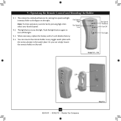
... switch plate with a 9-volt alkaline battery. 9-4. When necessary, replace the battery with the screws already in the switch plate. Fan Speed High Fan Speed Low Fan Speed Medium Fan Off Fan Light Steps 9-1 - 9-2 16 42616-01 • 02/02/10 • Hunter Fan Company Step 9-4 The remote has individual buttons for setting fan speed and light intensity. Push the light button again to turn off the light. 9-3. Or, you can mount the remote holder to the figure on the wall. Note: For best operation...
... switch plate with a 9-volt alkaline battery. 9-4. When necessary, replace the battery with the screws already in the switch plate. Fan Speed High Fan Speed Low Fan Speed Medium Fan Off Fan Light Steps 9-1 - 9-2 16 42616-01 • 02/02/10 • Hunter Fan Company Step 9-4 The remote has individual buttons for setting fan speed and light intensity. Push the light button again to turn off the light. 9-3. Or, you can mount the remote holder to the figure on the wall. Note: For best operation...
Owner's Manual
Page 17
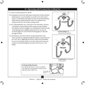
... will damage the finish. 10-4.T he blades on this fan have been treated with a direct breeze. Restart fan. Use a dry or slightly damp lint free cloth to the opposite position. Slide the reversing switch on the fan to clean the blades. 10 • Operating and Cleaning Your Ceiling Fan 10-1.Turn on electrical power to the fan. 10-2.Ceiling fans work best by blowing air downward (counterclockwise blade rotation) in warm weather to cool...
... will damage the finish. 10-4.T he blades on this fan have been treated with a direct breeze. Restart fan. Use a dry or slightly damp lint free cloth to the opposite position. Slide the reversing switch on the fan to clean the blades. 10 • Operating and Cleaning Your Ceiling Fan 10-1.Turn on electrical power to the fan. 10-2.Ceiling fans work best by blowing air downward (counterclockwise blade rotation) in warm weather to cool...
Owner's Manual
Page 18
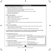
...://www.hunterfan.com. The following issues may arise if total wattage exceeds 190 Watts: Issue: Lights dim when turned on , replace fuse, or reset breaker. 2. Check the plug connection in the upper and lower switch housing. Tighten all blade and/or blade iron screws. 3. If your fan wobbles when operating, use the enclosed balancing kit and instructions to see if the blade is properly seated. fan does not move. 1. If you need parts or service assistance...
...://www.hunterfan.com. The following issues may arise if total wattage exceeds 190 Watts: Issue: Lights dim when turned on , replace fuse, or reset breaker. 2. Check the plug connection in the upper and lower switch housing. Tighten all blade and/or blade iron screws. 3. If your fan wobbles when operating, use the enclosed balancing kit and instructions to see if the blade is properly seated. fan does not move. 1. If you need parts or service assistance...
Parts Guide
Page 1
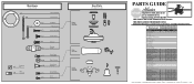
... Name Hanging System Kit Ceiling Plate Canopy Canopy Trim Ring Hanger Ball / Downrod Assembly Setscrew Low Profile Washer Canopy Screw Wood Screw Wood Screw Flat Washer Mounting Isolator Screw, Low Profile Switch Housing Assembly Switch Housing Cover Switch Housing Plug Button Blade Iron Set Blade Set Screw, Blade Iron Armature Light Kit Assembly Light bulb / Bulb Hardware Kit Blade Grommet Blade Assembly Screw Screw, Machine, 6-32 Wire Connector Mounting Isolator Screw, Switch Housing Assembly Balancing Kit Remote Control Receiver Remote Control Transmitter Remote Control Cradle Globe/Shade...
... Name Hanging System Kit Ceiling Plate Canopy Canopy Trim Ring Hanger Ball / Downrod Assembly Setscrew Low Profile Washer Canopy Screw Wood Screw Wood Screw Flat Washer Mounting Isolator Screw, Low Profile Switch Housing Assembly Switch Housing Cover Switch Housing Plug Button Blade Iron Set Blade Set Screw, Blade Iron Armature Light Kit Assembly Light bulb / Bulb Hardware Kit Blade Grommet Blade Assembly Screw Screw, Machine, 6-32 Wire Connector Mounting Isolator Screw, Switch Housing Assembly Balancing Kit Remote Control Receiver Remote Control Transmitter Remote Control Cradle Globe/Shade...


