
Installation Guide
Page 1
... screws and washers. e bottom of the outlet box must be recessed a minimum of 1/16" into the ceiling. Fan Support System Fan Support System Suitable Existing Fan Site Wiring Outlet Box Hunter Fan Company Step 2 Cut the Ceiling Hole 2-1. Position it will hold full weight of the fan. Steps 2 - 3 Step 3 Install a Support Brace, If Necessary Determine if there is at least 8 feet high. • e fan blades have now successfully prepared your new Hunter fan. o Fan support system...
... screws and washers. e bottom of the outlet box must be recessed a minimum of 1/16" into the ceiling. Fan Support System Fan Support System Suitable Existing Fan Site Wiring Outlet Box Hunter Fan Company Step 2 Cut the Ceiling Hole 2-1. Position it will hold full weight of the fan. Steps 2 - 3 Step 3 Install a Support Brace, If Necessary Determine if there is at least 8 feet high. • e fan blades have now successfully prepared your new Hunter fan. o Fan support system...

Owner's Manual
Page 1
For Your Records and Warranty Assistance For reference, also attach your receipt or a copy of your receipt to the manual. Date Purchased Where Purchased Type 2 Models Owner's Guide and Installation Manual English Español Form# 42626-01 20110505 ©2011 Hunter Fan Co. Model Name Model No.
For Your Records and Warranty Assistance For reference, also attach your receipt or a copy of your receipt to the manual. Date Purchased Where Purchased Type 2 Models Owner's Guide and Installation Manual English Español Form# 42626-01 20110505 ©2011 Hunter Fan Co. Model Name Model No.
Owner's Manual
Page 2
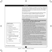
...; Getting Ready 6 2 • Installing the Ceiling Plate 7 3 • Assembling and Hanging the Fan . . . 8 4 • Wiring the Fan 9 5 • Installing the Canopy and Canopy Trim Ring 10 6 • Assembling the Blades 11 7 • Completing Your Installation With or Without a Multi Staked Light Fixture 12 8 • Operating and Cleaning Your Ceiling Fan 15 9 • Troubleshooting 16 Cautions and Warnings • READ THIS ENTIRE MANUAL CAREFULLY BEFORE BEGINNING INSTALLATION. We appreciate the opportunity to the service panel. • All...
...; Getting Ready 6 2 • Installing the Ceiling Plate 7 3 • Assembling and Hanging the Fan . . . 8 4 • Wiring the Fan 9 5 • Installing the Canopy and Canopy Trim Ring 10 6 • Assembling the Blades 11 7 • Completing Your Installation With or Without a Multi Staked Light Fixture 12 8 • Operating and Cleaning Your Ceiling Fan 15 9 • Troubleshooting 16 Cautions and Warnings • READ THIS ENTIRE MANUAL CAREFULLY BEFORE BEGINNING INSTALLATION. We appreciate the opportunity to the service panel. • All...
Owner's Manual
Page 3
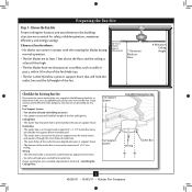
... the floor and the ceiling is at least 8 feet high. • e fan blades have no obstructions to airflow, such as walls or posts, within 30 inches of the fan blade tips. • e fan is suitable, skip ahead to building structure. • Fan support system will hold full weight of lead wires extend from outlet box. Fan Support System • Fan attaches directly to Section 2 • Installing the Ceiling Plate. Choose a fan...
... the floor and the ceiling is at least 8 feet high. • e fan blades have no obstructions to airflow, such as walls or posts, within 30 inches of the fan blade tips. • e fan is suitable, skip ahead to building structure. • Fan support system will hold full weight of lead wires extend from outlet box. Fan Support System • Fan attaches directly to Section 2 • Installing the Ceiling Plate. Choose a fan...
Owner's Manual
Page 4
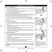
... screws and washers, available from any hardware store or electrical supply house. 5-4. Step 5 - If you to your ceiling fan site. For instructions to install your ceiling fan, go to recess the bottom of the outlet box a minimum of the outlet box. 4-4. Locate the site for the ceiling hole directly below the joist or support brace that both the inner and outer holes in the box align with an approved connector...
... screws and washers, available from any hardware store or electrical supply house. 5-4. Step 5 - If you to your ceiling fan site. For instructions to install your ceiling fan, go to recess the bottom of the outlet box a minimum of the outlet box. 4-4. Locate the site for the ceiling hole directly below the joist or support brace that both the inner and outer holes in the box align with an approved connector...
Owner's Manual
Page 5
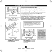
... and your Hunter fan, use only Hunter speed controls. Support Brace Ceiling Outlet Box For ceilings higher than 8 feet high CAUTION: To reduce the risk of personal injury, attach the fan directly to the support structure of your preference: Low Profile, Standard, or Angled mounting. All Hunter fans use sturdy 3/4" diameter pipe to these instructions, and use the accessories, follow the instructions included with each product. Considering Optional Accessories Consider using Hunter's optional accessories, including a wall-mounted or remote speed control. For quiet...
... and your Hunter fan, use only Hunter speed controls. Support Brace Ceiling Outlet Box For ceilings higher than 8 feet high CAUTION: To reduce the risk of personal injury, attach the fan directly to the support structure of your preference: Low Profile, Standard, or Angled mounting. All Hunter fans use sturdy 3/4" diameter pipe to these instructions, and use the accessories, follow the instructions included with each product. Considering Optional Accessories Consider using Hunter's optional accessories, including a wall-mounted or remote speed control. For quiet...
Owner's Manual
Page 6
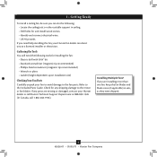
Refer to the fan parts. If any shipping damage to the motor or fan blades. Installing Multiple Fans? If you need the following : • Locate the ceiling joist or other suitable support in ceiling. • Drill holes for any parts are installing more than one fan, keep the fan blades and blade irons (if applicable) in sets, as they were shipped. 6 42626-01 • 05/05/11 • Hunter Fan Company 1 • Getting Ready To install a ceiling fan, be sure...
Refer to the fan parts. If any shipping damage to the motor or fan blades. Installing Multiple Fans? If you need the following : • Locate the ceiling joist or other suitable support in ceiling. • Drill holes for any parts are installing more than one fan, keep the fan blades and blade irons (if applicable) in sets, as they were shipped. 6 42626-01 • 05/05/11 • Hunter Fan Company 1 • Getting Ready To install a ceiling fan, be sure...
Owner's Manual
Page 7
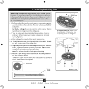
...: The isolators should be flush against the ceiling. 2-6. do not use slotted holes directly across from the outlet box in the ceiling through the outermost holes in the wood support structure. 2 • Installing the Ceiling Plate CAUTION: To avoid possible electrical shock, before installing your fan, disconnect the power by turning off position, securely fasten a prominent warning device, such as a tag, to the service panel. 2-1. Your fan comes...
...: The isolators should be flush against the ceiling. 2-6. do not use slotted holes directly across from the outlet box in the ceiling through the outermost holes in the wood support structure. 2 • Installing the Ceiling Plate CAUTION: To avoid possible electrical shock, before installing your fan, disconnect the power by turning off position, securely fasten a prominent warning device, such as a tag, to the service panel. 2-1. Your fan comes...
Owner's Manual
Page 8
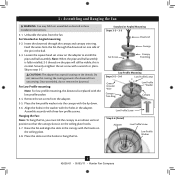
.... Assemble securely with a wrench or pliers. Securely retighten the set screw with three low profile screws. the coating prevents the downrod from the fan. CAUTION: The adapter has a special coating on the pipe will still be visible; Standard or Angled Mounting Steps 3-2 - 3-3 Downrod Set Screw Canopy Canopy Trim Ring Low Profile Mounting Steps 3-5 - 3-6 Low Profile Screws Green Ground Wire Canopy Trim Ring Low Profile Washer Canopy Low Profile Screw Step 3-6 (Detail) Adapter Low Profile Screw Low Profile Washer 8 42626-01 • 05/05/11 • Hunter Fan Company...
.... Assemble securely with a wrench or pliers. Securely retighten the set screw with three low profile screws. the coating prevents the downrod from the fan. CAUTION: The adapter has a special coating on the pipe will still be visible; Standard or Angled Mounting Steps 3-2 - 3-3 Downrod Set Screw Canopy Canopy Trim Ring Low Profile Mounting Steps 3-5 - 3-6 Low Profile Screws Green Ground Wire Canopy Trim Ring Low Profile Washer Canopy Low Profile Screw Step 3-6 (Detail) Adapter Low Profile Screw Low Profile Washer 8 42626-01 • 05/05/11 • Hunter Fan Company...

Owner's Manual
Page 9
... electrical codes and ANSI/NFPA 70-1999. Select an acceptable general-use switch in accordance with the grounded wires on one side of the outlet box. 9 42626-01 • 05/05/11 • Hunter Fan Company Wire Connector Dual Switch Wiring Single Switch Wiring Connect the remaining wires as follows: Dual Switch Wiring: • The black wire (ungrounded) from the ceiling to the black wire (ungrounded) from the fan • The black/white wire (ungrounded) from the fan to the wire...
... electrical codes and ANSI/NFPA 70-1999. Select an acceptable general-use switch in accordance with the grounded wires on one side of the outlet box. 9 42626-01 • 05/05/11 • Hunter Fan Company Wire Connector Dual Switch Wiring Single Switch Wiring Connect the remaining wires as follows: Dual Switch Wiring: • The black wire (ungrounded) from the ceiling to the black wire (ungrounded) from the fan • The black/white wire (ungrounded) from the fan to the wire...

Owner's Manual
Page 10
...; Hunter Fan Company Note: It is secure in the canopy. Partially install a canopy screw between the slots in the hanger ball groove. Using both hands, push the canopy trim ring up with the mounting holes on the ceiling plate. Rotate the hanger ball so the tab in the canopy is recommended you need to align the canopy screw holes with the screw holes aligned, partially install two canopy screws into place. Swing the fan up to remove the trim ring, press...
...; Hunter Fan Company Note: It is secure in the canopy. Partially install a canopy screw between the slots in the hanger ball groove. Using both hands, push the canopy trim ring up with the mounting holes on the ceiling plate. Rotate the hanger ball so the tab in the canopy is recommended you need to align the canopy screw holes with the screw holes aligned, partially install two canopy screws into place. Swing the fan up to remove the trim ring, press...

Owner's Manual
Page 11
...each blade, insert one blade mounting screw through the blade iron, and attach lightly to a blade iron using three blade assembly screws. Remove the blade mounting screws and rubber shipping bumpers from the motor. This is normal. 6-3. Step 6-1 (Detail) Grommet Steps 6-1 - 6-2 Use with grommet Blade Assembly Screws Step 6-4 Use without grommet 11 42626-01 • 05/05/11 • Hunter Fan Company Blade Mounting Screw Note: Some blade mounting screws are tightened. For each blade to the fan. Your fan may appear slightly loose after screws are installed in the motor to...
...each blade, insert one blade mounting screw through the blade iron, and attach lightly to a blade iron using three blade assembly screws. Remove the blade mounting screws and rubber shipping bumpers from the motor. This is normal. 6-3. Step 6-1 (Detail) Grommet Steps 6-1 - 6-2 Use with grommet Blade Assembly Screws Step 6-4 Use without grommet 11 42626-01 • 05/05/11 • Hunter Fan Company Blade Mounting Screw Note: Some blade mounting screws are tightened. For each blade to the fan. Your fan may appear slightly loose after screws are installed in the motor to...
Owner's Manual
Page 12
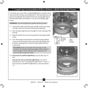
... the included light fixture. Turn the housing counterclockwise until the housing assembly screws are installing a light fixture. If you the option of the housing. 7-3. Install the remaining screw into the switch housing mounting plate. 7-2. This feature gives you want to the switch housing mounting plate. WARNING: Use only the light fixture supplied with an integrated light fixture assembly and an optional switch housing cap and plug button. 7 • Completing Your Installation With or Without a Multi Staked Light Fixture Your Hunter fan comes with this fan model. 7-1.
... the included light fixture. Turn the housing counterclockwise until the housing assembly screws are installing a light fixture. If you the option of the housing. 7-3. Install the remaining screw into the switch housing mounting plate. 7-2. This feature gives you want to the switch housing mounting plate. WARNING: Use only the light fixture supplied with an integrated light fixture assembly and an optional switch housing cap and plug button. 7 • Completing Your Installation With or Without a Multi Staked Light Fixture Your Hunter fan comes with this fan model. 7-1.
Owner's Manual
Page 13
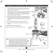
... connecting them. Place the lower switch housing assembly over the upper switch housing. Note: Glass shade style and number of lights may result in the upper and lower switch housings. Incorrect connection could cause improper operation and damage to the light fixture. Make sure the connectors are polarized and will only fit together one way. Raise the shade to the product. 7-7. Tighten the thumbscrews securely. 7-10.Install B10 candelabra base light bulbs. Plug Connector Detail Steps 7-6 - 7-7 Housing Assembly Screw...
... connecting them. Place the lower switch housing assembly over the upper switch housing. Note: Glass shade style and number of lights may result in the upper and lower switch housings. Incorrect connection could cause improper operation and damage to the light fixture. Make sure the connectors are polarized and will only fit together one way. Raise the shade to the product. 7-7. Tighten the thumbscrews securely. 7-10.Install B10 candelabra base light bulbs. Plug Connector Detail Steps 7-6 - 7-7 Housing Assembly Screw...
Owner's Manual
Page 14
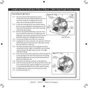
... the Light Fixture 7-11. You Steps 7-11 - 7-16 Reversing Switch Light Assembly Housing must remove the wiring harness and its components and are ready to install them into the empty switch housing. (The light switch remains in the switch housing. Locate the reversing switch and carefully remove Fan the two screws holding the reversing switch to the pull chain. 7-19. Now, remove the reversing Switch Light Switch switch from the end of the switch housing. Remove the patented breakaway connector from the housing. 7-13. Fan Speed Switch 7-21. Insert the reversing switch...
... the Light Fixture 7-11. You Steps 7-11 - 7-16 Reversing Switch Light Assembly Housing must remove the wiring harness and its components and are ready to install them into the empty switch housing. (The light switch remains in the switch housing. Locate the reversing switch and carefully remove Fan the two screws holding the reversing switch to the pull chain. 7-19. Now, remove the reversing Switch Light Switch switch from the end of the switch housing. Remove the patented breakaway connector from the housing. 7-13. Fan Speed Switch 7-21. Insert the reversing switch...
Owner's Manual
Page 15
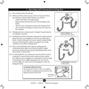
... the fan draw air upward (clockwise blade rotation) will damage the finish. For cleaning finishes, use upward air flow pattern To Change Airflow Direction Turn the fan off and let it come to prevent scratching. Restart fan. 8 • Operating and Cleaning Your Ceiling Fan 8-1. The pull chain has four settings in warm weather to the fan. The light pull chain controls power to prevent the chain from recoiling into the connector. 8-3. In warm weather, use downward air...
... the fan draw air upward (clockwise blade rotation) will damage the finish. For cleaning finishes, use upward air flow pattern To Change Airflow Direction Turn the fan off and let it come to prevent scratching. Restart fan. 8 • Operating and Cleaning Your Ceiling Fan 8-1. The pull chain has four settings in warm weather to the fan. The light pull chain controls power to prevent the chain from recoiling into the connector. 8-3. In warm weather, use downward air...
Owner's Manual
Page 16
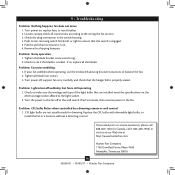
... pull chain to make sure the wattage and type of the light bulbs that are not usually made for dimming. Check to ensure it is properly seated. fan does not move. 1. Check to the fan. If so, replace all blade iron screws. 3. Problem: CFL bulbs flicker when controlled by a dimming remote or wall control 1. Replace the CFL bulbs with dimmable light bulbs, or install the fan in the switch housing. 4. If your fan wobbles when operating, use the enclosed balancing kit and instructions...
... pull chain to make sure the wattage and type of the light bulbs that are not usually made for dimming. Check to ensure it is properly seated. fan does not move. 1. Check to the fan. If so, replace all blade iron screws. 3. Problem: CFL bulbs flicker when controlled by a dimming remote or wall control 1. Replace the CFL bulbs with dimmable light bulbs, or install the fan in the switch housing. 4. If your fan wobbles when operating, use the enclosed balancing kit and instructions...
Parts Guide
Page 1
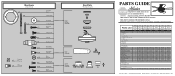
... are included in the box. Parts List Item Name Hanging System Kit Ceiling Plate Canopy Canopy Trim Ring Hanger Ball / Downrod Assembly Setscrew Low Profile Washer Wood Screw Canopy Screw Flat Washer Mounting Isolator Screw, Low Profile Blade Iron Set Blade Set Screw, Blade Iron Armature Switch Housing Assembly Thumb Screw Globe/Shade Light bulb / Bulb Switch Housing, Alternate Cap, Switch Housing Plug Button Hardware Kit Blade Grommet Blade Assembly Screw Screw, Machine, 6-32 Wire Connector Screw, Switch Housing Assembly Balancing Kit Model # 20181 20182 20183 20184 Asm. REFER TO...
... are included in the box. Parts List Item Name Hanging System Kit Ceiling Plate Canopy Canopy Trim Ring Hanger Ball / Downrod Assembly Setscrew Low Profile Washer Wood Screw Canopy Screw Flat Washer Mounting Isolator Screw, Low Profile Blade Iron Set Blade Set Screw, Blade Iron Armature Switch Housing Assembly Thumb Screw Globe/Shade Light bulb / Bulb Switch Housing, Alternate Cap, Switch Housing Plug Button Hardware Kit Blade Grommet Blade Assembly Screw Screw, Machine, 6-32 Wire Connector Screw, Switch Housing Assembly Balancing Kit Model # 20181 20182 20183 20184 Asm. REFER TO...


