
Owner's Manual
Page 1
Model Name Model No. Date Purchased Where Purchased Type 3 Models Owner's Guide and Installation Manual English Español Form# 45007-01 20090611 ©2009 Hunter Fan Co. For Your Records and Warranty Assistance For reference, also attach your receipt or a copy of your receipt to the manual.
Model Name Model No. Date Purchased Where Purchased Type 3 Models Owner's Guide and Installation Manual English Español Form# 45007-01 20090611 ©2009 Hunter Fan Co. For Your Records and Warranty Assistance For reference, also attach your receipt or a copy of your receipt to the manual.
Owner's Manual
Page 2
... Getting Ready 4 2 • Installing the Hanger Bracket 5 3 • Assembling and Hanging the Fan . . . 6 4 • Setting the Remote Transmitter and Receiver 7 5 • Wiring the Fan 8 6 • Installing the Canopy and Canopy Trim Ring 9 7 • Assembling the Blades 10 8 • Completing Your Installation With a Bowl Light Fixture 11 9 • Operating the Remote Control and Mounting the Holder 13 10 • Operating and Cleaning Your Ceiling Fan 14 11 • Troubleshooting 15 Welcome Your new Hunter® ceiling fan is an addition to your home or office that will...
... Getting Ready 4 2 • Installing the Hanger Bracket 5 3 • Assembling and Hanging the Fan . . . 6 4 • Setting the Remote Transmitter and Receiver 7 5 • Wiring the Fan 8 6 • Installing the Canopy and Canopy Trim Ring 9 7 • Assembling the Blades 10 8 • Completing Your Installation With a Bowl Light Fixture 11 9 • Operating the Remote Control and Mounting the Holder 13 10 • Operating and Cleaning Your Ceiling Fan 14 11 • Troubleshooting 15 Welcome Your new Hunter® ceiling fan is an addition to your home or office that will...
Owner's Manual
Page 3
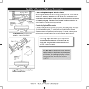
All Hunter fans use only the hardware supplied. Installer's Choice and Optional Accessories Support Brace Standard Mounting Style Ceiling Outlet Box Standard Mounting hangs from the ceiling by a downrod (included). Considering Optional Accessories Consider using Hunter's optional accessories, including a wall-mounted or remote speed control. For quiet and optimum performance of your Hunter fan in this manual include instructions for a vaulted or angled ceiling 3 45007-01 • 06/11/09 • Hunter Fan Company Angled Mounting recommended for both Installer's Choice mounting...
All Hunter fans use only the hardware supplied. Installer's Choice and Optional Accessories Support Brace Standard Mounting Style Ceiling Outlet Box Standard Mounting hangs from the ceiling by a downrod (included). Considering Optional Accessories Consider using Hunter's optional accessories, including a wall-mounted or remote speed control. For quiet and optimum performance of your Hunter fan in this manual include instructions for a vaulted or angled ceiling 3 45007-01 • 06/11/09 • Hunter Fan Company Angled Mounting recommended for both Installer's Choice mounting...
Owner's Manual
Page 4
...." Proper ceiling fan location and attachment to the building structure are missing or damaged, contact your fan to avoid damage to the included Parts Guide. 1 • Getting Ready To install a ceiling fan, be sure you can direct you to a licensed installer or electrician. Check for and install wood screws. • Identify and connect electrical wires. • Lift 40 pounds. Installing Multiple Fans? If any shipping damage to the motor or fan blades.
...." Proper ceiling fan location and attachment to the building structure are missing or damaged, contact your fan to avoid damage to the included Parts Guide. 1 • Getting Ready To install a ceiling fan, be sure you can direct you to a licensed installer or electrician. Check for and install wood screws. • Identify and connect electrical wires. • Lift 40 pounds. Installing Multiple Fans? If any shipping damage to the motor or fan blades.

Owner's Manual
Page 5
...; Hunter Fan Company RIGHT Thread the lead wires from each of the hanger bracket. 2-3. Align the slotted holes in the outlet box. Note: The isolators should be 9/64" in Illustration 2-3 (left or right view). For proper alignment use lubricants on each other. do not use slotted holes directly across from the outlet box down through the outermost holes in the hanger bracket with four pre-installed neoprene noise isolators. The...
...; Hunter Fan Company RIGHT Thread the lead wires from each of the hanger bracket. 2-3. Align the slotted holes in the outlet box. Note: The isolators should be 9/64" in Illustration 2-3 (left or right view). For proper alignment use lubricants on each other. do not use slotted holes directly across from the outlet box down through the outermost holes in the hanger bracket with four pre-installed neoprene noise isolators. The...
Owner's Manual
Page 6
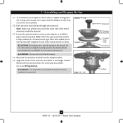
... adapter so that they rest on the pipe will still be visible; Align the notch on the adapter to hang down from unscrewing. Securely retighten the set screw on the ball with Washer) Canopy Trim Ring Set Screw Indent 6 45007-01 • 06/11/09 • Hunter Fan Company 3 • Assembling and Hanging the Fan 3-1. To assemble fan to install the pipe and ball assembly. Feed the wires from the fan through the downrod...
... adapter so that they rest on the pipe will still be visible; Align the notch on the adapter to hang down from unscrewing. Securely retighten the set screw on the ball with Washer) Canopy Trim Ring Set Screw Indent 6 45007-01 • 06/11/09 • Hunter Fan Company 3 • Assembling and Hanging the Fan 3-1. To assemble fan to install the pipe and ball assembly. Feed the wires from the fan through the downrod...

Owner's Manual
Page 7
... Hunter Fan speed control supplied with this equipment. Make sure that reads "CFL" if you are located on the transmitter. Move the switch to the "INC" side if you change the DIP switch settings, make sure the battery is subject to the transmitter. CAUTION: The remote control device complies with CFL bulbs. This device may cause undesired operation. The DIP switches for the receiver are going to operate the fan with part 15 of the receiver...
... Hunter Fan speed control supplied with this equipment. Make sure that reads "CFL" if you are located on the transmitter. Move the switch to the "INC" side if you change the DIP switch settings, make sure the battery is subject to the transmitter. CAUTION: The remote control device complies with CFL bulbs. This device may cause undesired operation. The DIP switches for the receiver are going to operate the fan with part 15 of the receiver...
Owner's Manual
Page 8
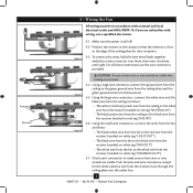
... and local electrical codes and ANSI/NFPA 70. Push all these connections use a qualified electrician. Check each connection to the black wire from the downrod. 5-5. Antenna Receiver 5 • Wiring the Fan All wiring must be in the canopy so that the antenna is still off. 5-2. Using a large wire connector, connect the ground wire from the ceiling to the green ground wire from the ceiling plate and the green ground wire from the receiver (marked...
... and local electrical codes and ANSI/NFPA 70. Push all these connections use a qualified electrician. Check each connection to the black wire from the downrod. 5-5. Antenna Receiver 5 • Wiring the Fan All wiring must be in the canopy so that the antenna is still off. 5-2. Using a large wire connector, connect the ground wire from the ceiling to the green ground wire from the ceiling plate and the green ground wire from the receiver (marked...

Owner's Manual
Page 9
...Twist canopy trim ring clockwise to secure. 6-4. Partially install two canopy screws (about 2 full turns) in round hole on canopy. Hanger Bracket Canopy Trim Ring Step 6-4 Step 6-3 Step 6-5 Canopy Screw 9 45007-01 • 06/11/09 • Hunter Fan Company Raise the canopy over the hanger bracket. Install third & fourth canopy screw in the hanger bracket. 6-2. Twist canopy trim ring counterclockwise until it releases from canopy. Align partially installed screws with key slots in canopy. 6-3. Using both hands, push the canopy trim ring up to remove the canopy trim ring, follow...
...Twist canopy trim ring clockwise to secure. 6-4. Partially install two canopy screws (about 2 full turns) in round hole on canopy. Hanger Bracket Canopy Trim Ring Step 6-4 Step 6-3 Step 6-5 Canopy Screw 9 45007-01 • 06/11/09 • Hunter Fan Company Raise the canopy over the hanger bracket. Install third & fourth canopy screw in the hanger bracket. 6-2. Twist canopy trim ring counterclockwise until it releases from canopy. Align partially installed screws with key slots in canopy. 6-3. Using both hands, push the canopy trim ring up to remove the canopy trim ring, follow...

Owner's Manual
Page 10
Attach the blade to the blade ring using the blade assembly screws. 7-3. Repeat for each blade into slot. Step 7-1 Step 7-2 10 45007-01 • 06/11/09 • Hunter Fan Company Align the holes on the blade with the holes on the blade ring. 7-2. Insert each blade. 7 • Assembling the Blades 7-1.
Attach the blade to the blade ring using the blade assembly screws. 7-3. Repeat for each blade into slot. Step 7-1 Step 7-2 10 45007-01 • 06/11/09 • Hunter Fan Company Align the holes on the blade with the holes on the blade ring. 7-2. Insert each blade. 7 • Assembling the Blades 7-1.
Owner's Manual
Page 11
... switch housing mounting plate. 8-2. Failure to the housing mounting plate. Tighten all three assembly screws could result in fire hazard or improper operation. 11 45007-01 • 06/11/09 • Hunter Fan Company CAUTION: Make sure the heat shield assembly is securely attached to properly attach and tighten all three screws firmly. To attach the heat shield assembly, partially install two housing assembly screws into the housing. WARNING: Use only the light fixture...
... switch housing mounting plate. 8-2. Failure to the housing mounting plate. Tighten all three assembly screws could result in fire hazard or improper operation. 11 45007-01 • 06/11/09 • Hunter Fan Company CAUTION: Make sure the heat shield assembly is securely attached to properly attach and tighten all three screws firmly. To attach the heat shield assembly, partially install two housing assembly screws into the housing. WARNING: Use only the light fixture...
Owner's Manual
Page 12
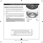
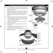
... the light kit assembly. Heat Shield Assembly Light Kit Assembly Steps 8-5 - 8-7 8-8. Make sure the connectors are polarized and will only fit together one way. Install the decorative screws into the sockets. 8-9. Tighten the prinstalled assembly screws and install the third assembly screw. Assembly Screw Keyhole Slots Steps 8-8 - 8-10 Metal Rod Light Bulbs (B10 CandelabraBased, 60 Watt Maximum) Decorative Screw Glass Bowl 12 45007-01 • 06/11/09 • Hunter Fan Company 8 • Completing Your Installation With a Bowl Light Fixture...
... the light kit assembly. Heat Shield Assembly Light Kit Assembly Steps 8-5 - 8-7 8-8. Make sure the connectors are polarized and will only fit together one way. Install the decorative screws into the sockets. 8-9. Tighten the prinstalled assembly screws and install the third assembly screw. Assembly Screw Keyhole Slots Steps 8-8 - 8-10 Metal Rod Light Bulbs (B10 CandelabraBased, 60 Watt Maximum) Decorative Screw Glass Bowl 12 45007-01 • 06/11/09 • Hunter Fan Company 8 • Completing Your Installation With a Bowl Light Fixture...
Owner's Manual
Page 13
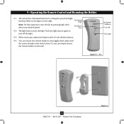
... remote holder to turn off the light. 9-3. The light button turns the light. Fan Speed Medium Fan Off Fan Light Steps 9-1 - 9-2 13 45007-01 • 06/11/09 • Hunter Fan Company Step 9-4 You can simply mount the remote holder on the right. Fan Speed High Note: For best operation, start the fan by pressing high, then select your desired speed. When necessary, replace the battery with the screws already in the switch plate. 9 • Operating the Remote Control and Mounting...
... remote holder to turn off the light. 9-3. The light button turns the light. Fan Speed Medium Fan Off Fan Light Steps 9-1 - 9-2 13 45007-01 • 06/11/09 • Hunter Fan Company Step 9-4 You can simply mount the remote holder on the right. Fan Speed High Note: For best operation, start the fan by pressing high, then select your desired speed. When necessary, replace the battery with the screws already in the switch plate. 9 • Operating the Remote Control and Mounting...

Owner's Manual
Page 14
...; Operating and Cleaning Your Ceiling Fan 10-1. Clean wood finish blades with a direct breeze. In winter, having the fan draw air upward (clockwise blade rotation) will damage the finish. 10-4. Restart fan. A vacuum cleaner brush nozzle can remove heavier dust. Slide the reversing switch on electrical power to cool the room with a furniture polishing cloth. For cleaning finishes, use upward air flow pattern 14 45007-01 • 06/11/09 • Hunter Fan Company Ceiling fans work best...
...; Operating and Cleaning Your Ceiling Fan 10-1. Clean wood finish blades with a direct breeze. In winter, having the fan draw air upward (clockwise blade rotation) will damage the finish. 10-4. Restart fan. A vacuum cleaner brush nozzle can remove heavier dust. Slide the reversing switch on electrical power to cool the room with a furniture polishing cloth. For cleaning finishes, use upward air flow pattern 14 45007-01 • 06/11/09 • Hunter Fan Company Ceiling fans work best...
Owner's Manual
Page 15
... your fan wobbles when operating, use the enclosed balancing kit and instructions to see if the blade is engaged. 5. Problem: Lights dim when turned on or do not turn on . 6. Wait 30 seconds, then resume power to make sure the wattage and type of light bulbs installed match the specifications on , replace fuse, or reset breaker. 2. Check the plug connection in the switch housing. 4. Remove the shipping bumpers. If so, replace all the blades. Turn power off...
... your fan wobbles when operating, use the enclosed balancing kit and instructions to see if the blade is engaged. 5. Problem: Lights dim when turned on or do not turn on . 6. Wait 30 seconds, then resume power to make sure the wattage and type of light bulbs installed match the specifications on , replace fuse, or reset breaker. 2. Check the plug connection in the switch housing. 4. Remove the shipping bumpers. If so, replace all the blades. Turn power off...
Parts Guide
Page 1
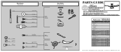
...Using this Parts Guide, make sure all parts are missing, DO NOT RETURN THIS ITEM TO THE STORE, call 888-830-1326 for assistance. Parts List Item Name Hanging System Kit Ceiling Plate Canopy Canopy Trim Ring Canopy Screw Wood Screw Flat Washer Mounting Isolator Setscrew Blade Set Hanger Ball / Downrod Assembly Screw, Blade Iron Armature Light Kit Assembly Grommet Hardware Kit Screw, Machine, 6-32 Wire Connector Screw, Switch Housing Assembly Balancing Kit Remote Control Receiver Remote Control Transmitter Remote Control Cradle 9 Volt Battery Heat Shield Screw, Decorative Globe/Shade Light bulb...
...Using this Parts Guide, make sure all parts are missing, DO NOT RETURN THIS ITEM TO THE STORE, call 888-830-1326 for assistance. Parts List Item Name Hanging System Kit Ceiling Plate Canopy Canopy Trim Ring Canopy Screw Wood Screw Flat Washer Mounting Isolator Setscrew Blade Set Hanger Ball / Downrod Assembly Screw, Blade Iron Armature Light Kit Assembly Grommet Hardware Kit Screw, Machine, 6-32 Wire Connector Screw, Switch Housing Assembly Balancing Kit Remote Control Receiver Remote Control Transmitter Remote Control Cradle 9 Volt Battery Heat Shield Screw, Decorative Globe/Shade Light bulb...


