Owners Manual
Page 2
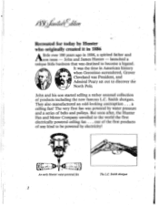
...100 years ago in American history when Geronimo surrendered, Grover Cleveland was destined to the world the first electrically powered ceiling fan . . But soon after, the Hunter Fan and Motor Company unveiled to become a legend. launched a unique little business that was President, and Admiral Peary set... out to be powered by electricity! a ceiling fan! John and James Hunter - one of the first products of any kind to discover the North Pole. Aysy:-;,,,k4/ Recreated for today by water ...
...100 years ago in American history when Geronimo surrendered, Grover Cleveland was destined to the world the first electrically powered ceiling fan . . But soon after, the Hunter Fan and Motor Company unveiled to become a legend. launched a unique little business that was President, and Admiral Peary set... out to be powered by electricity! a ceiling fan! John and James Hunter - one of the first products of any kind to discover the North Pole. Aysy:-;,,,k4/ Recreated for today by water ...
Owners Manual
Page 4
... non-metallic outlet box. TO ENSURE QUIET OPERATION AND FULL EFFICIENCY OF YOUR FAN, PLEASE FOLLOW ALL THE INSTRUC- NOTE TO INSTALLERS: Please leave this entire instruction manual thoroughly before servicing your Hunter Ceiling Fan. TY IS SHUT OFF AT MAIN PANEL BEFORE WIRING. All wiring must be... in place. If this fan. DO NOT HANG ON SINGLE "J" HOOK. Make absolutely certain all pipes and...
... non-metallic outlet box. TO ENSURE QUIET OPERATION AND FULL EFFICIENCY OF YOUR FAN, PLEASE FOLLOW ALL THE INSTRUC- NOTE TO INSTALLERS: Please leave this entire instruction manual thoroughly before servicing your Hunter Ceiling Fan. TY IS SHUT OFF AT MAIN PANEL BEFORE WIRING. All wiring must be... in place. If this fan. DO NOT HANG ON SINGLE "J" HOOK. Make absolutely certain all pipes and...
Owners Manual
Page 6
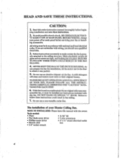
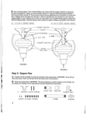
... pages 11 and 12. 8-8 1/2 FT CEILING 8 1/2 FT & UP CEILING 5. Wire the fan. If your installation site. Run electrical power off. Install canopy. The Basic Steps to Take to 81/z 1, use Step 413 of fan. Hang your fan. Install the ceiling mounting hardware. Place bushing in top of.... 2. Hang fan. Check motor, sacked parts, and blades. Securely install hanger bracket, pipe and canopies (1 or 2) in bracket and install bracket. tions and connect ground wire to hanger bracket. If your ceiling is 8' to Install Your Ceiling Fan 1., Select your ceiling is 812/ ...
... pages 11 and 12. 8-8 1/2 FT CEILING 8 1/2 FT & UP CEILING 5. Wire the fan. If your installation site. Run electrical power off. Install canopy. The Basic Steps to Take to 81/z 1, use Step 413 of fan. Hang your fan. Install the ceiling mounting hardware. Place bushing in top of.... 2. Hang fan. Check motor, sacked parts, and blades. Securely install hanger bracket, pipe and canopies (1 or 2) in bracket and install bracket. tions and connect ground wire to hanger bracket. If your ceiling is 8' to Install Your Ceiling Fan 1., Select your ceiling is 812/ ...
Owners Manual
Page 8
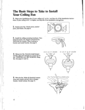
...ceilings are available from Hunter. - 8 - 8 1/2 FT. B. Do not remove the coating. BRACKET & MTG SCREWS 0 II SHORT PIPE ADAPTOR HANGER BRKT TT CANOPY & BLADE SCREWS 8 7" PIPE BUSHING Fan mounting height: Your Limited Edition fan comes with an additional set of hardware to mount the fan to ceilings... coating on the threads. U - CEILING HEIGHT 8 1/2 FT & UP CEILING HEIGHT HANGER BRACKET CANOPY SETSCREWS . 2 3/4" PIPE 7" PIPE HANGER ADAPTOR MOTOR AND CASE FIGURE 2 T FIGURE 3 Step 2: Inspect Fan A. CAUTION: Never lift the fan by the motor wires. Check the sacked...
...ceilings are available from Hunter. - 8 - 8 1/2 FT. B. Do not remove the coating. BRACKET & MTG SCREWS 0 II SHORT PIPE ADAPTOR HANGER BRKT TT CANOPY & BLADE SCREWS 8 7" PIPE BUSHING Fan mounting height: Your Limited Edition fan comes with an additional set of hardware to mount the fan to ceilings... coating on the threads. U - CEILING HEIGHT 8 1/2 FT & UP CEILING HEIGHT HANGER BRACKET CANOPY SETSCREWS . 2 3/4" PIPE 7" PIPE HANGER ADAPTOR MOTOR AND CASE FIGURE 2 T FIGURE 3 Step 2: Inspect Fan A. CAUTION: Never lift the fan by the motor wires. Check the sacked...
Owners Manual
Page 9
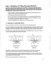
...to the joist as shown in center of joist. Drill (2) " diameter holes 2-9/16" apart through the back of Ceiling Mounting Hardware CAUTION: YOUR HUNTER CEILING FAN WEIGHS UP TO 50 LBS. MOUNTING BRACKET MUST BE DIRECTLY SUPPORTED BY THE BUILDING STRUCTURE. • When inspecting or... preparing installation site where wiring is available, hiake sure electricity is -not centered under an existing ceiling joist (see Figures 4 and 5) it...
...to the joist as shown in center of joist. Drill (2) " diameter holes 2-9/16" apart through the back of Ceiling Mounting Hardware CAUTION: YOUR HUNTER CEILING FAN WEIGHS UP TO 50 LBS. MOUNTING BRACKET MUST BE DIRECTLY SUPPORTED BY THE BUILDING STRUCTURE. • When inspecting or... preparing installation site where wiring is available, hiake sure electricity is -not centered under an existing ceiling joist (see Figures 4 and 5) it...
Owners Manual
Page 11
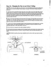
... is centered in correct order may weigh up to , be followed in . Step 4A: Hanging the Fan on it will go on the shaft. A. Slide pipe over the hanger pipe. See Fig. 7.... pipe onto motorshaft. YOU MUST BE CERTAIN. TO TIGHTEN THE SET SCREW HOLDING THIS PIPE ONTO THE FAN. See Fig. 7. Use the canopy with the small hole orr first. The other canopy is all...Slide the canopy over the wires, then over wires, putting the end with the Hunter nameplate on an 8-foot Ceiling CAUTION: Your fan may result in the rubber bushing. Slide the canopy down to perforin these steps completely...
... is centered in correct order may weigh up to , be followed in . Step 4A: Hanging the Fan on it will go on the shaft. A. Slide pipe over the hanger pipe. See Fig. 7.... pipe onto motorshaft. YOU MUST BE CERTAIN. TO TIGHTEN THE SET SCREW HOLDING THIS PIPE ONTO THE FAN. See Fig. 7. Use the canopy with the small hole orr first. The other canopy is all...Slide the canopy over the wires, then over wires, putting the end with the Hunter nameplate on an 8-foot Ceiling CAUTION: Your fan may result in the rubber bushing. Slide the canopy down to perforin these steps completely...
Owners Manual
Page 12
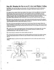
A. Back out set screw in the hanger bracket. Use pliers to 50 pounds. Place the canopy without the Hunter nameplate over the pipe first, with the large opening away from the motor. Then put the second canopy over the wires, putting the end with ... SURE BOTH ENDS OF THE PIN ARE OUTSIDE THE HANGER BRACKET. Step 4B: Hanging the Fan on an 81/2-foot and Higher Ceiling CAUTION: Your fan may result in the fan falling. All of each canopy. Perform steps A through D with fan. Remove short, stepped, black motor adapter from the carton. It is tight. Be certain...
A. Back out set screw in the hanger bracket. Use pliers to 50 pounds. Place the canopy without the Hunter nameplate over the pipe first, with the large opening away from the motor. Then put the second canopy over the wires, putting the end with ... SURE BOTH ENDS OF THE PIN ARE OUTSIDE THE HANGER BRACKET. Step 4B: Hanging the Fan on an 81/2-foot and Higher Ceiling CAUTION: Your fan may result in the fan falling. All of each canopy. Perform steps A through D with fan. Remove short, stepped, black motor adapter from the carton. It is tight. Be certain...
Owners Manual
Page 13
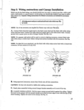
...employed, cap the black with white stripe motor lead with the accessory. Connect ground wire to national and local codes which may city by Hunter may void your fan-with the top of hanger bracket. See Fig. 1113. Tighten the screw in the canopy. All wiring must conform to green screw ... to the black motor lead and the black with white stripe motor lead (see note). Lift the second canopy up 'and hold it against the ceiling. NOTE: If a light kit is even with a pull cord, a wall switch or a speed control. Using approved connectors, secure them firmly onto all wire connections....
...employed, cap the black with white stripe motor lead with the accessory. Connect ground wire to national and local codes which may city by Hunter may void your fan-with the top of hanger bracket. See Fig. 1113. Tighten the screw in the canopy. All wiring must conform to green screw ... to the black motor lead and the black with white stripe motor lead (see note). Lift the second canopy up 'and hold it against the ceiling. NOTE: If a light kit is even with a pull cord, a wall switch or a speed control. Using approved connectors, secure them firmly onto all wire connections....
Owners Manual
Page 14
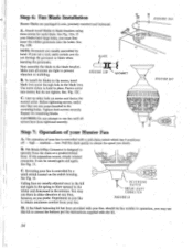
...hold in operation, you prefer. Make sure all screws have large holes, you desire. high - See Fig. 13. Step 6: Fan Blade Installation 11 Hunter Blades are packaged in the mounting holes. If you use this separation occurs, simply reinsert connector. BLADE FIGURE 12B QFtomMET B. To ... provided with a pull-chain switch which has 4 positions: off - If your fart, should the fan wobble in place. CAUTION: Do not attempt to prevent vibration or wobbling. low. Ceiling fans are tight to run them in either direction at a predetermined force. See. See Fig. 13. ...
...hold in operation, you prefer. Make sure all screws have large holes, you desire. high - See Fig. 13. Step 6: Fan Blade Installation 11 Hunter Blades are packaged in the mounting holes. If you use this separation occurs, simply reinsert connector. BLADE FIGURE 12B QFtomMET B. To ... provided with a pull-chain switch which has 4 positions: off - If your fart, should the fan wobble in place. CAUTION: Do not attempt to prevent vibration or wobbling. low. Ceiling fans are tight to run them in either direction at a predetermined force. See. See Fig. 13. ...
Owners Manual
Page 16
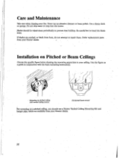
.... Horizontal beam mount i'ior mounting on pitched ceiling with the basic mounting instructions. 4 - Be careful hot to your Hunter dealer. 16 If blades are available from your fan. Order replacement parts from your ceiling. Care and Maintenance 'Bike care when cleaning your Hunter dealer. Never use a Hunter Vaulted Ceiling Mounting Kit and hanger pipe* which are cracked...
.... Horizontal beam mount i'ior mounting on pitched ceiling with the basic mounting instructions. 4 - Be careful hot to your Hunter dealer. 16 If blades are available from your fan. Order replacement parts from your ceiling. Care and Maintenance 'Bike care when cleaning your Hunter dealer. Never use a Hunter Vaulted Ceiling Mounting Kit and hanger pipe* which are cracked...
Owners Manual
Page 17
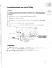
... receive 14/ "xl12/ " expansion shield anchor, Rawl No. 1055 or equal. (Not furnished.) Install shield in Concrete Ceiling CAUTION: A 1. A-,47a61 ° a 0 0 4 o A o. Bracket (Furnished with fan) Expansion shield anchor, set in the vicinity of the fan per the basic installation instructions. 17 • Installation in holes, observing all cautions above. Proceed with a suitable carbide...
... receive 14/ "xl12/ " expansion shield anchor, Rawl No. 1055 or equal. (Not furnished.) Install shield in Concrete Ceiling CAUTION: A 1. A-,47a61 ° a 0 0 4 o A o. Bracket (Furnished with fan) Expansion shield anchor, set in the vicinity of the fan per the basic installation instructions. 17 • Installation in holes, observing all cautions above. Proceed with a suitable carbide...
Owners Manual
Page 18
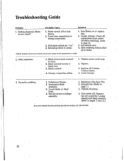
...4. Pull switch cord. 4. Blade cracked. 4. Replace all screws. 4. Lower canopy. 3. Loose blades or blade irons. 4. Run power off while checking). Support fan very carefully. Pull-chain switch not "on or replace fuse. 2. Blade irons loosely screwed to page 13. 3. Power turned off or fuse blown. 2. Loosen ... Probable Cause Solution 1. Tighten all 4 blades. do not rotate* 1. Refer to rotor. 2. Blade screwed loosely to blade iron. 3. Canopy contacting ceiling. 1. Reversing switch in center. • 1. Inadequate blade clearance. 3.
...4. Pull switch cord. 4. Blade cracked. 4. Replace all screws. 4. Lower canopy. 3. Loose blades or blade irons. 4. Run power off while checking). Support fan very carefully. Pull-chain switch not "on or replace fuse. 2. Blade irons loosely screwed to page 13. 3. Power turned off or fuse blown. 2. Loosen ... Probable Cause Solution 1. Tighten all 4 blades. do not rotate* 1. Refer to rotor. 2. Blade screwed loosely to blade iron. 3. Canopy contacting ceiling. 1. Reversing switch in center. • 1. Inadequate blade clearance. 3.


