
Owners Manual
Page 1
guilclioil 8eit6osova100 eig/14 Owner's Manual Read and Save These Instructions 1
guilclioil 8eit6osova100 eig/14 Owner's Manual Read and Save These Instructions 1
Owners Manual
Page 2
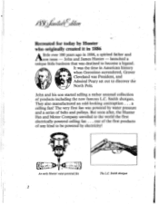
...little business that was President, and Admiral Peary set out to become a legend. John and his son started selling a rather unusual collection of products including the now famous L.C. The very first fan was powered by Hunter who originally created it in 1886 A little over... first products of any kind to the world the first electrically powered ceiling fan . . John and James Hunter - They also manufactured an odd-looking contraption . . . But soon after, the Hunter Fan and Motor Company unveiled to be powered by electricity! Aysy:-;,,,k4/ Recreated for today by water pressure and ...
...little business that was President, and Admiral Peary set out to become a legend. John and his son started selling a rather unusual collection of products including the now famous L.C. The very first fan was powered by Hunter who originally created it in 1886 A little over... first products of any kind to the world the first electrically powered ceiling fan . . John and James Hunter - They also manufactured an odd-looking contraption . . . But soon after, the Hunter Fan and Motor Company unveiled to be powered by electricity! Aysy:-;,,,k4/ Recreated for today by water pressure and ...

Owners Manual
Page 3
... consumers want today. Created in all of the state of that,event, Hunter has recreated the fan that conjures up fantasies of this fan. the 1886 Limited Edition Commemorative Fan. Deeply sculptured floral design throughout, the ornate cast-iron housing revolves with real wood "wing-tip" blades, just some of the unique collector features of a bygone and romantic...
... consumers want today. Created in all of the state of that,event, Hunter has recreated the fan that conjures up fantasies of this fan. the 1886 Limited Edition Commemorative Fan. Deeply sculptured floral design throughout, the ornate cast-iron housing revolves with real wood "wing-tip" blades, just some of the unique collector features of a bygone and romantic...
Owners Manual
Page 4
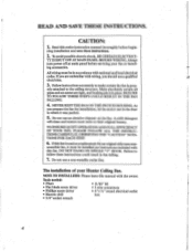
... used as a replacement for installation, let the motor rest in the liner in fan falling. 7. erly attached to make certain the fan is prop- NEVER REST THE FAN ON THE SWITCH HOUSING. Do not use a non-metallic outlet box. Follow instructions accurately to the ceiling structure. TIONS FOR EACH STEP. • 6. NOTE TO INSTALLERS: Please leave this entire instruction manual thoroughly before servicing your Hunter Ceiling Fan. A mild detergent will clean...
... used as a replacement for installation, let the motor rest in the liner in fan falling. 7. erly attached to make certain the fan is prop- NEVER REST THE FAN ON THE SWITCH HOUSING. Do not use a non-metallic outlet box. Follow instructions accurately to the ceiling structure. TIONS FOR EACH STEP. • 6. NOTE TO INSTALLERS: Please leave this entire instruction manual thoroughly before servicing your Hunter Ceiling Fan. A mild detergent will clean...
Owners Manual
Page 5
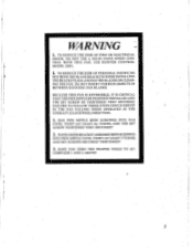
... THESE STEPS COULD RESULT IN THE FAN FALLING WHEN OPERATED IN THE UPDRAFT (CLOCKWISE) DIRECTION. 1. TO REDUCE THE RISK OF PERSONAL INJURY, DO NOT BEND THE BLADE BRACKETS WHEN INSTALLING THE BRACKETS, BALANCING THE BLADES OR CLEANING THE FAN. HAS HANGER BRACKET ASSEMBLY BEEN SCREWED INTO PIPE NIPPLE UNTIL TIGHT (AT LEAST 3 TURNS) AND SET SCREWS SECURELY TIGHTENED? 3. USE HUNTER CONTROL MODEL 22691. 2. HAVE YOU USED THE PROPER TOOLS TO ACCOMPLISH...
... THESE STEPS COULD RESULT IN THE FAN FALLING WHEN OPERATED IN THE UPDRAFT (CLOCKWISE) DIRECTION. 1. TO REDUCE THE RISK OF PERSONAL INJURY, DO NOT BEND THE BLADE BRACKETS WHEN INSTALLING THE BRACKETS, BALANCING THE BLADES OR CLEANING THE FAN. HAS HANGER BRACKET ASSEMBLY BEEN SCREWED INTO PIPE NIPPLE UNTIL TIGHT (AT LEAST 3 TURNS) AND SET SCREWS SECURELY TIGHTENED? 3. USE HUNTER CONTROL MODEL 22691. 2. HAVE YOU USED THE PROPER TOOLS TO ACCOMPLISH...
Owners Manual
Page 6
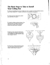
... fan. Install the ceiling mounting hardware. Run electrical power off. See page 9. 4. Hang fan. Wire the fan. Support electrical box. Hang your fan. See page 8. 3. Drill holes for bracket. Securely install hanger bracket, pipe and canopies (1 or 2) in bracket and install bracket. tions. If your ceiling is 8' to 81/z 1, use Step 413 of fan. Make all electrical connec- See page 13. 6 Place bushing in top of the installation instrii9tions. 2. See pages 11 and 12. 8-8 1/2 FT CEILING 8 1/2 FT & UP CEILING 5. Install canopy. TIGHTEN ALL SET SCREWS...
... fan. Install the ceiling mounting hardware. Run electrical power off. See page 9. 4. Hang fan. Wire the fan. Support electrical box. Hang your fan. See page 8. 3. Drill holes for bracket. Securely install hanger bracket, pipe and canopies (1 or 2) in bracket and install bracket. tions. If your ceiling is 8' to 81/z 1, use Step 413 of fan. Make all electrical connec- See page 13. 6 Place bushing in top of the installation instrii9tions. 2. See pages 11 and 12. 8-8 1/2 FT CEILING 8 1/2 FT & UP CEILING 5. Install canopy. TIGHTEN ALL SET SCREWS...

Owners Manual
Page 7
... rotating fan blades. Mounting site should be within 24" of the tips of the blades (see page 18 for proper operation of the room, often-replacing a light fix- Check for trouble-shooting, BE SURE THE PIPE NIPPLE IS SECURELY SCREWED INTO ME NECK OF THE FAN AND THE HANGER BRACKET, AND THE SET SCREWS FOR THE HANGER BRACKET AND MOTOR ARE TIGHT. Step 1: Pre-Installation A. Install fan blades. Be sure all blades are...
... rotating fan blades. Mounting site should be within 24" of the tips of the blades (see page 18 for proper operation of the room, often-replacing a light fix- Check for trouble-shooting, BE SURE THE PIPE NIPPLE IS SECURELY SCREWED INTO ME NECK OF THE FAN AND THE HANGER BRACKET, AND THE SET SCREWS FOR THE HANGER BRACKET AND MOTOR ARE TIGHT. Step 1: Pre-Installation A. Install fan blades. Be sure all blades are...
Owners Manual
Page 8
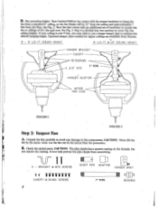
... fan to hang the fan from a standard 8' ceiling, so the fan blades will be 12" from the ceiling and approximately 7 feet from Hunter. - 8 - 8 1/2 FT. CEILING HEIGHT 8 1/2 FT & UP CEILING HEIGHT HANGER BRACKET CANOPY SETSCREWS . 2 3/4" PIPE 7" PIPE HANGER ADAPTOR MOTOR AND CASE FIGURE 2 T FIGURE 3 Step 2: Inspect Fan A. Fan mounting height: Your Limited Edition fan comes with an additional set of 812/ feet and over 9 feet, you may wish to use a longer hanger pipe to cover...
... fan to hang the fan from a standard 8' ceiling, so the fan blades will be 12" from the ceiling and approximately 7 feet from Hunter. - 8 - 8 1/2 FT. CEILING HEIGHT 8 1/2 FT & UP CEILING HEIGHT HANGER BRACKET CANOPY SETSCREWS . 2 3/4" PIPE 7" PIPE HANGER ADAPTOR MOTOR AND CASE FIGURE 2 T FIGURE 3 Step 2: Inspect Fan A. Fan mounting height: Your Limited Edition fan comes with an additional set of 812/ feet and over 9 feet, you may wish to use a longer hanger pipe to cover...
Owners Manual
Page 9
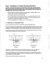
... sufficient size. If the mounting site is "off electricity at fuse box or circuit breaker panel. • All wiring must -be necessary to hang fan. THE FOLLOWING PRECAUTIONS MUST BE TAKEN FOR SAFETY AND TO ENSURE THAT YOUR FAN IS SECURELY MOUNTED TO THE CEILING. Install rubber bushing hi hanger bracket before assembling the parts to an unsupported electrical outlet. • The wood joist chosen for hole pattern. Replacing an...
... sufficient size. If the mounting site is "off electricity at fuse box or circuit breaker panel. • All wiring must -be necessary to hang fan. THE FOLLOWING PRECAUTIONS MUST BE TAKEN FOR SAFETY AND TO ENSURE THAT YOUR FAN IS SECURELY MOUNTED TO THE CEILING. Install rubber bushing hi hanger bracket before assembling the parts to an unsupported electrical outlet. • The wood joist chosen for hole pattern. Replacing an...

Owners Manual
Page 10
... have to be a minimum 2"x 4" size and;securely mounted between the ceiling joists with a cross member. Use the (2) bracket screws to secure the hanger bracket and outlet box to rein- A I FIGURE 6 2. There may already be two holes at the main panel before assembling the parts to the center of the cross member. 3. force the mounting site with nails or wood screws. Install rubber bushing in Fig. 4 and...
... have to be a minimum 2"x 4" size and;securely mounted between the ceiling joists with a cross member. Use the (2) bracket screws to secure the hanger bracket and outlet box to rein- A I FIGURE 6 2. There may already be two holes at the main panel before assembling the parts to the center of the cross member. 3. force the mounting site with nails or wood screws. Install rubber bushing in Fig. 4 and...
Owners Manual
Page 11
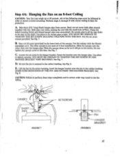
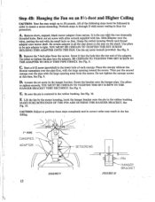
... Fig. 7. Use the set ,screw with alien wrench supplied with motor resting in . Grasp the switch housing firmly and thread hanger pipe onto motorshaft. Use pliers to 50 pounds. Slide pipe over the hanger pipe. C Loosen the set screw in the rubber bushing. Step 4A: Hanging the Fan on an 8-foot Ceiling CAUTION: Your fan may result in the fan falling. 1 I I I I I I CANOPY SETSCREWS PIPE FIGURE 7 PIN BRACkET FIGURE 8 order to...
... Fig. 7. Use the set ,screw with alien wrench supplied with motor resting in . Grasp the switch housing firmly and thread hanger pipe onto motorshaft. Use pliers to 50 pounds. Slide pipe over the hanger pipe. C Loosen the set screw in the rubber bushing. Step 4A: Hanging the Fan on an 8-foot Ceiling CAUTION: Your fan may result in the fan falling. 1 I I I I I I CANOPY SETSCREWS PIPE FIGURE 7 PIN BRACkET FIGURE 8 order to...
Owners Manual
Page 12
... rubber bushing. Back out set screw in the lower hole of the following steps must be sure adapter is all the way down to 50 pounds. Lift the fan by the motor housing, hook the hanger bracket onto the pin in liner for protection. CAUTION: Failure to ensure a secure mounting. C I I 7" PIPE CANOPIES ADAPTOR SETSCREWS A FIGURE 9 12 .11 PIN FIGURE 10 HANGER BRACKET All of each canopy. Use...
... rubber bushing. Back out set screw in the lower hole of the following steps must be sure adapter is all the way down to 50 pounds. Lift the fan by the motor housing, hook the hanger bracket onto the pin in liner for protection. CAUTION: Failure to ensure a secure mounting. C I I 7" PIPE CANOPIES ADAPTOR SETSCREWS A FIGURE 9 12 .11 PIN FIGURE 10 HANGER BRACKET All of each canopy. Use...
Owners Manual
Page 13
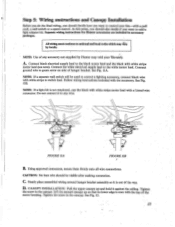
... fan-with a Listed wire connector. Follow wiring instructions included with white stripe to green screw on side of the motor housing. Using approved connectors, secure them firmly onto all wire connections. Do not connect it against the ceiling. C Neatly place assembled wiring around hanger bracket assembly so it is even with white stripe motor lead (see note). Tighten the screw in the canopy. All wiring must conform to the white motor lead. Connect black electrical supply lead to control...
... fan-with a Listed wire connector. Follow wiring instructions included with white stripe to green screw on side of the motor housing. Using approved connectors, secure them firmly onto all wire connections. Do not connect it against the ceiling. C Neatly place assembled wiring around hanger bracket assembly so it is even with white stripe motor lead (see note). Tighten the screw in the canopy. All wiring must conform to the white motor lead. Connect black electrical supply lead to control...
Owners Manual
Page 14
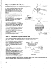
... in sets, precisely matched and balanced. I, FIGURE 12A FIGURE 1.2C Step 7: Operation of your fart, should the fan wobble in the blade iron. C. Ceiling fans are not cross-threaded in the summer. Before tightening screws, make certain you desire. C. Pull the chain gently to blow upward in the winter and downWard in the mounting holes. A. Line up other hole on the switch housing. Reversing your fan is controlled...
... in sets, precisely matched and balanced. I, FIGURE 12A FIGURE 1.2C Step 7: Operation of your fart, should the fan wobble in the blade iron. C. Ceiling fans are not cross-threaded in the summer. Before tightening screws, make certain you desire. C. Pull the chain gently to blow upward in the winter and downWard in the mounting holes. A. Line up other hole on the switch housing. Reversing your fan is controlled...

Owners Manual
Page 15
...Loosen the two screws holding reversing switch. Remove both switches into light kit adapter supplied. Attach light kit adapter to this fan adaptable for a light kit installation. Remove screws and carefully lower switch housing cover, Loosen and remove nut holding pull chain switch. B. C Proceed with installation of a Light Kit You may add any wire connections. See Fig. 15. FIGURE 14 REVERSING SWITCH PULL CHAIN SWITCH NUT SWITCH HOUSING COVER SCREWS FIGURE 15 :15 Please follow the instructions below and then proceed with any Hunter listed light kit to fan with two 6-32...
...Loosen the two screws holding reversing switch. Remove both switches into light kit adapter supplied. Attach light kit adapter to this fan adaptable for a light kit installation. Remove screws and carefully lower switch housing cover, Loosen and remove nut holding pull chain switch. B. C Proceed with installation of a Light Kit You may add any wire connections. See Fig. 15. FIGURE 14 REVERSING SWITCH PULL CHAIN SWITCH NUT SWITCH HOUSING COVER SCREWS FIGURE 15 :15 Please follow the instructions below and then proceed with any Hunter listed light kit to fan with two 6-32...
Owners Manual
Page 16
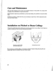
... buildup. Order replacement parts from your ceiling. Mounting on Pitched or Beam Ceilings Choose the specific figure below showing the mounting approriate to repair them. Never use a Hunter Vaulted Ceiling Mounting Kit and hanger pipe* which are cracked, or blade irons bent, do not attempt to your Hunter dealer. 16 Care and Maintenance 'Bike care when cleaning your Hunter dealer. If blades are available from your fan. Installation on pitched ceiling with the basic mounting instructions...
... buildup. Order replacement parts from your ceiling. Mounting on Pitched or Beam Ceilings Choose the specific figure below showing the mounting approriate to repair them. Never use a Hunter Vaulted Ceiling Mounting Kit and hanger pipe* which are cracked, or blade irons bent, do not attempt to your Hunter dealer. 16 Care and Maintenance 'Bike care when cleaning your Hunter dealer. If blades are available from your fan. Installation on pitched ceiling with the basic mounting instructions...
Owners Manual
Page 17
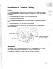
... bracket screws must be turned easily (by the manufacturer of the mounting holes. 5. P - 0 r ''' A .6. • D D a O 0 r:D, -A, A 4 0 A 0 GO P Ac A o, o , o t' ID A 0 0 63 A o r) i.., a D 0 .., 0:. For concrete mounting, the drilled hole must be recommended by hand), do not hang fan. Bracket (Furnished with fan) Expansion shield anchor, set in the vicinity of the an- The holes must be made with ceiling (anchor not furnished) Installation A. of the fan per the basic installation instructions. 17...
... bracket screws must be turned easily (by the manufacturer of the mounting holes. 5. P - 0 r ''' A .6. • D D a O 0 r:D, -A, A 4 0 A 0 GO P Ac A o, o , o t' ID A 0 0 63 A o r) i.., a D 0 .., 0:. For concrete mounting, the drilled hole must be recommended by hand), do not hang fan. Bracket (Furnished with fan) Expansion shield anchor, set in the vicinity of the an- The holes must be made with ceiling (anchor not furnished) Installation A. of the fan per the basic installation instructions. 17...
Owners Manual
Page 18
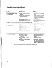
.... 18 Tighten. • 3. Check all connections (turn by hand, contact your nearest service representative or dealer. 2. Fan not secure on :' 4. blades - Blade cracked. 4. Canopy contacting ceiling. 1. Lower canopy. 3. Relocate fan. (Refer to page 7.) 3. Power turned off or fuse blown. 2. Unbalanced blades. 2. Excessive wobbling. 1. Support fan very carefully. Contact dealer. 4. Nothing happens; Pull-chain switch not "on hanger assembly. 1. lbrn power on or replace fuse. 2. Pull switch cord. 4. Tighten screws until snug. 2. Rebalance. (See Step 7D...
.... 18 Tighten. • 3. Check all connections (turn by hand, contact your nearest service representative or dealer. 2. Fan not secure on :' 4. blades - Blade cracked. 4. Canopy contacting ceiling. 1. Lower canopy. 3. Relocate fan. (Refer to page 7.) 3. Power turned off or fuse blown. 2. Unbalanced blades. 2. Excessive wobbling. 1. Support fan very carefully. Contact dealer. 4. Nothing happens; Pull-chain switch not "on hanger assembly. 1. lbrn power on or replace fuse. 2. Pull switch cord. 4. Tighten screws until snug. 2. Rebalance. (See Step 7D...
Owners Manual
Page 19
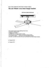
... easy way with the new way to use Hunter cross brace hanger bracket. 16" Model 22733 24" Model 22771 How to hang a Hunter fan where there's no bother with Hunter's cross brace hanger bracket. • An installer's dream . . . The new Hunter cross brace hanger bratket. NOT INCLUDED WITH FAN • • ID ID Fr= • Fits neatly through existing lighting fixture hole. • Expands to dig into joists. • Supports up to 60...
... easy way with the new way to use Hunter cross brace hanger bracket. 16" Model 22733 24" Model 22771 How to hang a Hunter fan where there's no bother with Hunter's cross brace hanger bracket. • An installer's dream . . . The new Hunter cross brace hanger bratket. NOT INCLUDED WITH FAN • • ID ID Fr= • Fits neatly through existing lighting fixture hole. • Expands to dig into joists. • Supports up to 60...
Owners Manual
Page 20
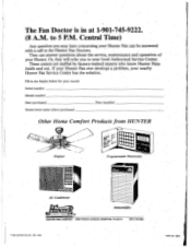
... where purchased Date installed Other Home Comfort Products from HUNTER TO:381T2 41, Original Programmable Thermostat 4.411.4iLL azzaaralr.=122S Air Conditioner Dehumidifier , SINCE 1886 wsvmsmimmilimmari HUNTER FAN COMPANY 2500 FRISCO AVENUE, MEMPHIS, TN 38114 (901) 743-1360 1988 HUNTER FAN CO.. Or, they will refer you may have concerning your Hunter Fan can answer questions about the service, maintenance and operation of your nearby Hunter Fan Service...
... where purchased Date installed Other Home Comfort Products from HUNTER TO:381T2 41, Original Programmable Thermostat 4.411.4iLL azzaaralr.=122S Air Conditioner Dehumidifier , SINCE 1886 wsvmsmimmilimmari HUNTER FAN COMPANY 2500 FRISCO AVENUE, MEMPHIS, TN 38114 (901) 743-1360 1988 HUNTER FAN CO.. Or, they will refer you may have concerning your Hunter Fan can answer questions about the service, maintenance and operation of your nearby Hunter Fan Service...


