
Manual
Page 2
... of electric shock do not return this owner's manual. entre les plafond selon les cas. Manufacturing code Contents Important Safeguards 3 Power Canister Description 4 Installation...5 Location...5 Mounting...5 How to use outdoors or on wet surfaces. CANAVAC SYSTEMS INC ONTARIO, CANADA MODEL ...2 Verification of date of your sales receipt to speak with a customer service representative; Desérie XXXXXXXXXXXX Mount at hoover.com and follow the service center locator link to individual brance circuit. Brancher a une derivation distincte AVERTISSEMENT:Pour reduire les...
... of electric shock do not return this owner's manual. entre les plafond selon les cas. Manufacturing code Contents Important Safeguards 3 Power Canister Description 4 Installation...5 Location...5 Mounting...5 How to use outdoors or on wet surfaces. CANAVAC SYSTEMS INC ONTARIO, CANADA MODEL ...2 Verification of date of your sales receipt to speak with a customer service representative; Desérie XXXXXXXXXXXX Mount at hoover.com and follow the service center locator link to individual brance circuit. Brancher a une derivation distincte AVERTISSEMENT:Pour reduire les...
Manual
Page 3
... when wearing open toe shoes or sandals. • Disconnect hose from wall inlet and cord from electrical outlet before servicing the power unit. • Do not unplug by Hoover; WARNING: TO REDUCE THE RISK OF FIRE, ELECTRIC SHOCK OR INJURY: • Do not use and before unplugging. •...; Do not use powered nozzle outdoors. • Keep hair, loose clothing, fingers, feet and all controls before servicing motorized nozzle. • The ...
... when wearing open toe shoes or sandals. • Disconnect hose from wall inlet and cord from electrical outlet before servicing the power unit. • Do not unplug by Hoover; WARNING: TO REDUCE THE RISK OF FIRE, ELECTRIC SHOCK OR INJURY: • Do not use and before unplugging. •...; Do not use powered nozzle outdoors. • Keep hair, loose clothing, fingers, feet and all controls before servicing motorized nozzle. • The ...
Manual
Page 4
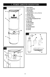
Motor Module 2. Overload Protector 8. Mounting Bracket 15. Vac Pan 1.3 13 14 15 1.2 9 10 3 11 7 6 16 8 4 Dust Container (contains items 11, 13, 14, 15 & 16) 5. Filtration Body 6. POWER CANISTER DESCRIPTION 1 1 2 12 1. Motor Exhaust Port 3. Mounting Bar 4. ON-OFF Switch 7. Power Cord 10. Data Label 11. Vac Cap 16. Hose Inlet Port 13. 90° Elbow 14. Low Voltage Receptacle (24 volt) 9. 1.1 6 5 4 1. Exhaust Muffler 12.
Motor Module 2. Overload Protector 8. Mounting Bracket 15. Vac Pan 1.3 13 14 15 1.2 9 10 3 11 7 6 16 8 4 Dust Container (contains items 11, 13, 14, 15 & 16) 5. Filtration Body 6. POWER CANISTER DESCRIPTION 1 1 2 12 1. Motor Exhaust Port 3. Mounting Bar 4. ON-OFF Switch 7. Power Cord 10. Data Label 11. Vac Cap 16. Hose Inlet Port 13. 90° Elbow 14. Low Voltage Receptacle (24 volt) 9. 1.1 6 5 4 1. Exhaust Muffler 12.
Manual
Page 5
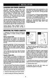
...screws. Drill a second pilot hole using a lower hole on the back of the central vacuum. 2.1 2.2 TOP MOUNTING A BRACKET 5. Plug the power cord in the basement, utility room, garage or any corner wall, to allow proper cooling to an electrical outlet. UNDER NO CIRCUMSTANCES SHOULD AN ... Mark the other remote area, except where exposed to weather, and convenient to the motor. Connect the 24 Volt wires coming from the Power Canister. Align the bracket over the mark. x 1-3/4" (4.4 cm) pilot hole. Tighten the exhaust connection with the 3" (7.6cm) gear...
...screws. Drill a second pilot hole using a lower hole on the back of the central vacuum. 2.1 2.2 TOP MOUNTING A BRACKET 5. Plug the power cord in the basement, utility room, garage or any corner wall, to allow proper cooling to an electrical outlet. UNDER NO CIRCUMSTANCES SHOULD AN ... Mark the other remote area, except where exposed to weather, and convenient to the motor. Connect the 24 Volt wires coming from the Power Canister. Align the bracket over the mark. x 1-3/4" (4.4 cm) pilot hole. Tighten the exhaust connection with the 3" (7.6cm) gear...
Manual
Page 6
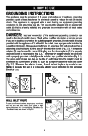
... Fig 3.3. 3.3 A B 6 HOW TO USE Grounding Instructions This appliance must be installed by the Canadian Electrical Code. 3.1 A 3.2 E D F BGROUNDING OUTLET BOX G C Wall Inlet Valve To start your Power Canister, simply plug your hose end into an appropriate outlet (B) that looks like (F) extending from the adapter must be connected to a 2-pole receptacle (E) if a properly...
... Fig 3.3. 3.3 A B 6 HOW TO USE Grounding Instructions This appliance must be installed by the Canadian Electrical Code. 3.1 A 3.2 E D F BGROUNDING OUTLET BOX G C Wall Inlet Valve To start your Power Canister, simply plug your hose end into an appropriate outlet (B) that looks like (F) extending from the adapter must be connected to a 2-pole receptacle (E) if a properly...
Manual
Page 7
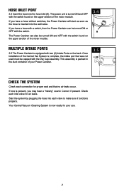
... Check each connection for air leaks. Start the system by plugging the hose into the hose inlet (A). If you have a hose with a switch, then the Power Canister can also be turned ON and OFF with the switch found on the back. If one is equipped with the switch. Correct if present... must be turned ON or OFF with two (2) Intake Ports on the upper section of the motor module. The power unit is complete, the intake port that no air leaks occur. The Power Canister can be capped with the switch found on the upper section of your use. 7 This assembly is packed...
... Check each connection for air leaks. Start the system by plugging the hose into the hose inlet (A). If you have a hose with a switch, then the Power Canister can also be turned ON and OFF with the switch found on the back. If one is equipped with the switch. Correct if present... must be turned ON or OFF with two (2) Intake Ports on the upper section of the motor module. The power unit is complete, the intake port that no air leaks occur. The Power Canister can be capped with the switch found on the upper section of your use. 7 This assembly is packed...
Manual
Page 8
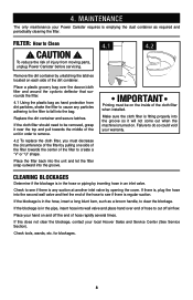
... deflector that surrounds the filter. 4.1 Using the plastic bag as required and periodically cleaning the filter. for blockages. 8 MAINTENANCE The only maintenance your local Hoover Sales and Service Center (See Service Section). 4. Check tools, wands, etc. Check to see if there is , plug the hose into the bag.... If the blockage is emptying the dust container as hand protection from moving parts, unplug Power Canister before servicing. If this does not clear the blockage, contact your Power Canister requires is in an inlet valve.
... deflector that surrounds the filter. 4.1 Using the plastic bag as required and periodically cleaning the filter. for blockages. 8 MAINTENANCE The only maintenance your local Hoover Sales and Service Center (See Service Section). 4. Check tools, wands, etc. Check to see if there is , plug the hose into the bag.... If the blockage is emptying the dust container as hand protection from moving parts, unplug Power Canister before servicing. If this does not clear the blockage, contact your Power Canister requires is in an inlet valve.
Manual
Page 9
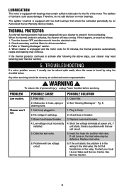
... above steps, your cleaner may be lubricated periodically by an Authorized Hoover Warranty Service Dealer. Low voltage circuit incorrectly installed. 5. Defective wall valve. 6. Short low voltage terminals at power unit, if unit starts, there is unplugged and the motor cools...filters for the life of the motor. Not firmly plugged in firmly. 2. Pg. 8. 1. Blown fuse/tripped breaker. 4. unplug Power Canister before servicing. TROUBLESHOOTING If a minor problem occurs, it usually can be done by an authorized service representative. ! Insert the hose...
... above steps, your cleaner may be lubricated periodically by an Authorized Hoover Warranty Service Dealer. Low voltage circuit incorrectly installed. 5. Defective wall valve. 6. Short low voltage terminals at power unit, if unit starts, there is unplugged and the motor cools...filters for the life of the motor. Not firmly plugged in firmly. 2. Pg. 8. 1. Blown fuse/tripped breaker. 4. unplug Power Canister before servicing. TROUBLESHOOTING If a minor problem occurs, it usually can be done by an authorized service representative. ! Insert the hose...

Manual
Page 10
...-Fri 8am-7pm EST. If you . • For a referral of the Power Canister.) Please do not return this product to Hoover®, Inc., Company in delay. Service To obtain approved Hoover® service and genuine Hoover® parts, locate the nearest Authorized Hoover® Warranty Service Dealer (Depot) by the complete model number when requesting...
...-Fri 8am-7pm EST. If you . • For a referral of the Power Canister.) Please do not return this product to Hoover®, Inc., Company in delay. Service To obtain approved Hoover® service and genuine Hoover® parts, locate the nearest Authorized Hoover® Warranty Service Dealer (Depot) by the complete model number when requesting...
Manual
Page 11
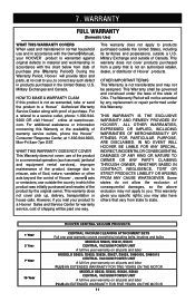
...FROM ANY CAUSE WHATSOEVER. This warranty gives you . During the Warranty Period, Hoover¨ will not be paid one year warranty covers everything including belts, brushes and bulbs MODELS S5605, S5610, S5615 CENTRAL VACUUM POWER UNIT A full five year warranty on all parts and labor MODELS S5620,... by any such defect in products purchased in the United States, U.S. The Warranty Period will provide labor and parts, at www.hoover. For additional assistance or information concerning this Warranty. This warranty does not apply to correct any replacement or repair performed under the ...
...FROM ANY CAUSE WHATSOEVER. This warranty gives you . During the Warranty Period, Hoover¨ will not be paid one year warranty covers everything including belts, brushes and bulbs MODELS S5605, S5610, S5615 CENTRAL VACUUM POWER UNIT A full five year warranty on all parts and labor MODELS S5620,... by any such defect in products purchased in the United States, U.S. The Warranty Period will provide labor and parts, at www.hoover. For additional assistance or information concerning this Warranty. This warranty does not apply to correct any replacement or repair performed under the ...

