Installation Instructions
Page 1
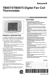
...fan status, and remote setback • Proportional plus Integral (P+I) control algorithm for precision temperature regulation. • Single Setpoint and Heat/Cool setpoint methods for your application: • TB6575A1000 - 2-pipe or 4-pipe with seasonal/ manual/automatic heat/cool changeover; 120/240 Vac. • TB6575B1000... links between wiring terminals allow manual control of system operation, fan speed, and temperature setpoint adjustment. • Digital display of a key. TB6575/TB8575 Digital Fan Coil Thermostats PRODUCT DESCRIPTION The TB6575 and TB8575 are : • Heating...
...fan status, and remote setback • Proportional plus Integral (P+I) control algorithm for precision temperature regulation. • Single Setpoint and Heat/Cool setpoint methods for your application: • TB6575A1000 - 2-pipe or 4-pipe with seasonal/ manual/automatic heat/cool changeover; 120/240 Vac. • TB6575B1000... links between wiring terminals allow manual control of system operation, fan speed, and temperature setpoint adjustment. • Digital display of a key. TB6575/TB8575 Digital Fan Coil Thermostats PRODUCT DESCRIPTION The TB6575 and TB8575 are : • Heating...
Installation Instructions
Page 2
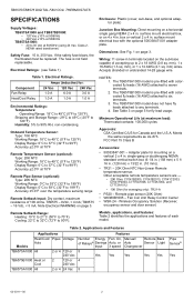
...Auto TB6575A1000 All 2 or 4 120 or 240 Vac TB6575B1000 Heat or 2 Cool 120 or 240 Vac TB8575A1000 All 2 or 4 24 Vac Features Number Energy Fan: On, Manual/ Remote Back of each model. If the safety fuse blows, the thermostat must be replaced. Electrical Ratings: (see Table 1).... single gang NEMA 2 x 4 in . (10 mm)). • TR21 - 20K Ohm NTC Non-Linear Remote temperature sensor. TB6575/TB8575 DIGITAL FAN COIL THERMOSTATS SPECIFICATIONS Supply Voltages: TB6575A1000 and TB6575B1000: • 120 Vac ±10% at 50/60Hz • 240 Vac ±10% at 50/60Hz TB8575A1000: • 20 to...
...Auto TB6575A1000 All 2 or 4 120 or 240 Vac TB6575B1000 Heat or 2 Cool 120 or 240 Vac TB8575A1000 All 2 or 4 24 Vac Features Number Energy Fan: On, Manual/ Remote Back of each model. If the safety fuse blows, the thermostat must be replaced. Electrical Ratings: (see Table 1).... single gang NEMA 2 x 4 in . (10 mm)). • TR21 - 20K Ohm NTC Non-Linear Remote temperature sensor. TB6575/TB8575 DIGITAL FAN COIL THERMOSTATS SPECIFICATIONS Supply Voltages: TB6575A1000 and TB6575B1000: • 120 Vac ±10% at 50/60Hz • 240 Vac ±10% at 50/60Hz TB8575A1000: • 20 to...
Installation Instructions
Page 3
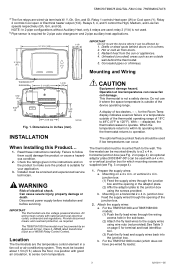
...occur. For the TB8575A1000 model (which mounting screws are supplied (see Fig. 2 on a 4 x 4 in a fan coil or air-conditioning system. TB6575/TB8575 DIGITAL FAN COIL THERMOSTATS a The five relays are used; NOTE: In 2-pipe configurations without Auxiliary Heat, only 4 relays are wired via terminals..., and Low fan speeds respectively (Gh, Gm, and Gl). Drafts or dead spots behind the thermostat. 5. Disconnect power supply before installation and before servicing. The optional freeze protect feature should be powered by : (29) 1. For the TB6575A1000 and TB6575B1000 models: (1) ...
...occur. For the TB8575A1000 model (which mounting screws are supplied (see Fig. 2 on a 4 x 4 in a fan coil or air-conditioning system. TB6575/TB8575 DIGITAL FAN COIL THERMOSTATS a The five relays are used; NOTE: In 2-pipe configurations without Auxiliary Heat, only 4 relays are wired via terminals..., and Low fan speeds respectively (Gh, Gm, and Gl). Drafts or dead spots behind the thermostat. 5. Disconnect power supply before installation and before servicing. The optional freeze protect feature should be powered by : (29) 1. For the TB6575A1000 and TB6575B1000 models: (1) ...

Installation Instructions
Page 4
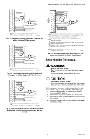
... TB6575A1000 and TB6575B1000 models have the following meaning: • C: Common 24 Vac • Gh: High speed fan relay • Gl: Low speed fan relay • Gm: Medium speed fan relay • L: Line voltage power (120/240 Vac) 62-0311-05 4 TB6575/TB8575 DIGITAL FAN COIL THERMOSTATS (1) Attach ...the supply wires directly to the sub-base. 7. Mounting on a horizontal 2 x 4 in . Use the provided safety screw to secure the thermostat main body to the terminals on the wall. 5. junction box...
... TB6575A1000 and TB6575B1000 models have the following meaning: • C: Common 24 Vac • Gh: High speed fan relay • Gl: Low speed fan relay • Gm: Medium speed fan relay • L: Line voltage power (120/240 Vac) 62-0311-05 4 TB6575/TB8575 DIGITAL FAN COIL THERMOSTATS (1) Attach ...the supply wires directly to the sub-base. 7. Mounting on a horizontal 2 x 4 in . Use the provided safety screw to secure the thermostat main body to the terminals on the wall. 5. junction box...
Installation Instructions
Page 5
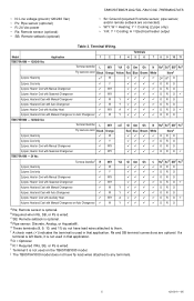
... ORO 2 pipes; Heat and Cool with Manual Changeover 9 W/Y 99 9 9 ORO 2 pipes; Heat or Cool with Manual Changeover or Auto Changeover 9 W Y 99 9 9 ORO TB6575B1000 - 120/240 Vac Terminal Identifier L W/Y n/ai Gl Gm Gh N Rsa Scb SBc Psd 2 pipes; Heat and Cool with Auxiliary Heat 9 W/Y A 9 9 9 9 O ... (optional) • R: 24 Vac power • Rs: Remote sensor (optional) • SB: Remote setback (optional) TB6575/TB8575 DIGITAL FAN COIL THERMOSTATS • Sc: Ground (required if remote sensor, pipe sensor, and/or remote setback are optional. Remote sensor is wired. e These ...
... ORO 2 pipes; Heat and Cool with Manual Changeover 9 W/Y 99 9 9 ORO 2 pipes; Heat or Cool with Manual Changeover or Auto Changeover 9 W Y 99 9 9 ORO TB6575B1000 - 120/240 Vac Terminal Identifier L W/Y n/ai Gl Gm Gh N Rsa Scb SBc Psd 2 pipes; Heat and Cool with Auxiliary Heat 9 W/Y A 9 9 9 9 O ... (optional) • R: 24 Vac power • Rs: Remote sensor (optional) • SB: Remote setback (optional) TB6575/TB8575 DIGITAL FAN COIL THERMOSTATS • Sc: Ground (required if remote sensor, pipe sensor, and/or remote setback are optional. Remote sensor is wired. e These ...
Installation Instructions
Page 6
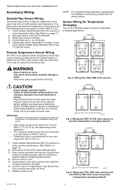
...ISU) 6 and 7 to prevent drafts from large inductive loads such as an alternative to the pipe. 4. M27559 Fig. 4. Failure to Rs and Sc thermostat terminals. 3. mm) depending on page 11). 2. Wire sensor to follow the installation instructions provided with auxiliary heat changeover. Push excess wire back into the hole... Check Installer Setup Number (ISU) 5 to ensure it is set for 2 pipes auto and 2 pipes heat and cool with the remote sensor. TB6575/TB8575 DIGITAL FAN COIL THERMOSTATS Accessory Wiring Remote Pipe Sensor Wiring The remote pipe sensor is used as the remote sensor.
...ISU) 6 and 7 to prevent drafts from large inductive loads such as an alternative to the pipe. 4. M27559 Fig. 4. Failure to Rs and Sc thermostat terminals. 3. mm) depending on page 11). 2. Wire sensor to follow the installation instructions provided with auxiliary heat changeover. Push excess wire back into the hole... Check Installer Setup Number (ISU) 5 to ensure it is set for 2 pipes auto and 2 pipes heat and cool with the remote sensor. TB6575/TB8575 DIGITAL FAN COIL THERMOSTATS Accessory Wiring Remote Pipe Sensor Wiring The remote pipe sensor is used as the remote sensor.
Installation Instructions
Page 7
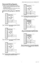
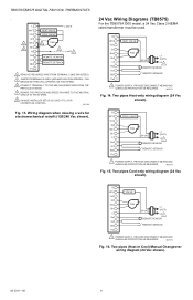
... N N Rs REMOTE SENSOR Sc SB REMOTE SETBACK PIPE SENSOR Ps M27571 Fig. 12. TB6575/TB8575 DIGITAL FAN COIL THERMOSTATS Thermostat Wiring Diagrams The figures in this section illustrate typical wiring for: • TB6575A1000 and TB6575B1000 fan coil thermostats, which is 24 Vac powered. Refer to Fig. 7-Fig. 13, beginning on page 8. 120/240 Vac Wiring Diagrams (TB6575A/ B) L L (HOT) W/Y HEAT...
... N N Rs REMOTE SENSOR Sc SB REMOTE SETBACK PIPE SENSOR Ps M27571 Fig. 12. TB6575/TB8575 DIGITAL FAN COIL THERMOSTATS Thermostat Wiring Diagrams The figures in this section illustrate typical wiring for: • TB6575A1000 and TB6575B1000 fan coil thermostats, which is 24 Vac powered. Refer to Fig. 7-Fig. 13, beginning on page 8. 120/240 Vac Wiring Diagrams (TB6575A/ B) L L (HOT) W/Y HEAT...
Installation Instructions
Page 8
...C L2 1 Rs REMOTE SENSOR Sc SB REMOTE SETBACK Ps 1 POWER SUPPLY. PROVIDE DISCONNECT MEANS AND OVERLOAD PROTECTION AS REQUIRED. R W/Y COOL VALVE Y/A GI Gm FAN L1 Gh 24 VAC (HOT) C L2 1 Rs REMOTE SENSOR Sc SB REMOTE SETBACK Ps 1 POWER SUPPLY. PROVIDE DISCONNECT MEANS AND OVERLOAD PROTECTION AS REQUIRED. Two...Two pipes Cool-only wiring diagram (24 Vac shown). M27575 Fig. 16. Two pipes Heat-only wiring diagram (24 Vac shown). TB6575/TB8575 DIGITAL FAN COIL THERMOSTATS . M27574 Fig. 15. L W/Y Y/A GI 1 Gm Gh 2 N Rs Sc SB Ps HEAT VALVE COOL VALVE L (HOT...
...C L2 1 Rs REMOTE SENSOR Sc SB REMOTE SETBACK Ps 1 POWER SUPPLY. PROVIDE DISCONNECT MEANS AND OVERLOAD PROTECTION AS REQUIRED. R W/Y COOL VALVE Y/A GI Gm FAN L1 Gh 24 VAC (HOT) C L2 1 Rs REMOTE SENSOR Sc SB REMOTE SETBACK Ps 1 POWER SUPPLY. PROVIDE DISCONNECT MEANS AND OVERLOAD PROTECTION AS REQUIRED. Two...Two pipes Cool-only wiring diagram (24 Vac shown). M27575 Fig. 16. Two pipes Heat-only wiring diagram (24 Vac shown). TB6575/TB8575 DIGITAL FAN COIL THERMOSTATS . M27574 Fig. 15. L W/Y Y/A GI 1 Gm Gh 2 N Rs Sc SB Ps HEAT VALVE COOL VALVE L (HOT...
Installation Instructions
Page 9
...6 CHANGE INSTALLER SETUP IS CODE 9 TO 2 FOR 2 SPEED FAN CONTROL. Carefully follow the thermostat removal directions. Use both hands to Fig. 21 and perform the following steps: 1. TB6575/TB8575 DIGITAL FAN COIL THERMOSTATS R W/Y VALVE Y/A GI Gm FAN Gh 24 VAC L1 (HOT) C L2 1 Rs REMOTE SENSOR... Sc SB REMOTE SETBACK Ps PIPE SENSOR 1 POWER SUPPLY. R W/Y VALVE Y/A AUX GI Gm FAN Gh 24 VAC L1 (HOT) C L2 1 ...
...6 CHANGE INSTALLER SETUP IS CODE 9 TO 2 FOR 2 SPEED FAN CONTROL. Carefully follow the thermostat removal directions. Use both hands to Fig. 21 and perform the following steps: 1. TB6575/TB8575 DIGITAL FAN COIL THERMOSTATS R W/Y VALVE Y/A GI Gm FAN Gh 24 VAC L1 (HOT) C L2 1 Rs REMOTE SENSOR... Sc SB REMOTE SETBACK Ps PIPE SENSOR 1 POWER SUPPLY. R W/Y VALVE Y/A AUX GI Gm FAN Gh 24 VAC L1 (HOT) C L2 1 ...
Installation Instructions
Page 10
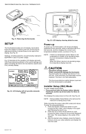
... shows all display segments for two seconds, enters a self-test mode for the two buttons, System and Fan), actually display. Power overload will damage the thermostat. Installer Setup (ISU) Mode To enter Installer Setup Mode: • Press and hold both the System button (labeled Heat/Cool) and the Up Arrow ... screen. Press the Up or Down Arrow buttons to store your value selection and display the next ISU code. 62-0311-05 10 The thermostat has a safety fuse rated at 15 A/ 250 Vac. TB6575/TB8575 DIGITAL FAN COIL THERMOSTATS UP AND DOWN ARROW BUTTONS Set to prevent fire if the...
... shows all display segments for two seconds, enters a self-test mode for the two buttons, System and Fan), actually display. Power overload will damage the thermostat. Installer Setup (ISU) Mode To enter Installer Setup Mode: • Press and hold both the System button (labeled Heat/Cool) and the Up Arrow ... screen. Press the Up or Down Arrow buttons to store your value selection and display the next ISU code. 62-0311-05 10 The thermostat has a safety fuse rated at 15 A/ 250 Vac. TB6575/TB8575 DIGITAL FAN COIL THERMOSTATS UP AND DOWN ARROW BUTTONS Set to prevent fire if the...
Installation Instructions
Page 11
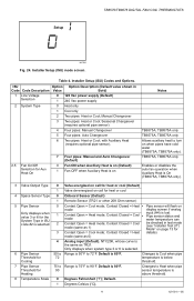
... (same as 1) input (#4) is 80°F. 90 Changes to 90°F. Default is lost. with Auxiliary Heat (requires optional pipe sensor). 2.5 Fan On/Off Selection for Cooling 50 to Range is below threshold. 7 Pipe Sensor Threshold for heat or cool 4 Space Sensor Type 0 Onboard Sensor ...to Cool when pipe temperature is 50°F to 72°F. Default. 1 Degrees Celsius (°C). 11 62-0311-05 Setup TB6575/TB8575 DIGITAL FAN COIL THERMOSTATS M27585 Fig. 24. Contact Closed = Heat • Pipe sensor will flash on when pipes have cold water (TB6575A, TB8575A only). ...
... (same as 1) input (#4) is 80°F. 90 Changes to 90°F. Default is lost. with Auxiliary Heat (requires optional pipe sensor). 2.5 Fan On/Off Selection for Cooling 50 to Range is below threshold. 7 Pipe Sensor Threshold for heat or cool 4 Space Sensor Type 0 Onboard Sensor ...to Cool when pipe temperature is 50°F to 72°F. Default. 1 Degrees Celsius (°C). 11 62-0311-05 Setup TB6575/TB8575 DIGITAL FAN COIL THERMOSTATS M27585 Fig. 24. Contact Closed = Heat • Pipe sensor will flash on when pipes have cold water (TB6575A, TB8575A only). ...
Installation Instructions
Page 12
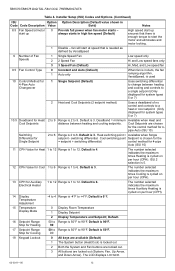
...is 1 to 6. Default. Installer Setup (ISU) Codes and Options. (Continued) ISU Option Option Description (Default value shown in high fan speed (Default) 9 Number of no control and controls to a heat or cool setpoint. (Only displayed for Cooling 18 Keypad Lockout -4... up always starts in Code Code Description Value Bold) 8.5 Fan Speed at speed that is 3. 13 CPH for the = setpoint + switching differential. Default is enough torque to 90 0 Display Room Temperature Display Setpoint Display Temperature and Setpoint; TB6575/TB8575 DIGITAL FAN COIL THERMOSTATS Table 4.
...is 1 to 6. Default. Installer Setup (ISU) Codes and Options. (Continued) ISU Option Option Description (Default value shown in high fan speed (Default) 9 Number of no control and controls to a heat or cool setpoint. (Only displayed for Cooling 18 Keypad Lockout -4... up always starts in Code Code Description Value Bold) 8.5 Fan Speed at speed that is 3. 13 CPH for the = setpoint + switching differential. Default is enough torque to 90 0 Display Room Temperature Display Setpoint Display Temperature and Setpoint; TB6575/TB8575 DIGITAL FAN COIL THERMOSTATS Table 4.

Installation Instructions
Page 13
... for 72 to Range is satisfied. This displays all segments of the screen. 3. for 3 seconds and thermostat will not be selectable when ISU 19 is 79°F. Stat cycles On Heat when room temperature reaches 40°F (4°C), and disables activate when the application is 72...Occupied; 30 minute delay going from Occupied to store your value selection and display the next IT code. 13 62-0311-05 TB6575/TB8575 DIGITAL FAN COIL THERMOSTATS Table 4. Installer Setup (ISU) Codes and Options. (Continued) ISU Option Option Description (Default value shown in the center of the ...
... for 72 to Range is satisfied. This displays all segments of the screen. 3. for 3 seconds and thermostat will not be selectable when ISU 19 is 79°F. Stat cycles On Heat when room temperature reaches 40°F (4°C), and disables activate when the application is 72...Occupied; 30 minute delay going from Occupied to store your value selection and display the next IT code. 13 62-0311-05 TB6575/TB8575 DIGITAL FAN COIL THERMOSTATS Table 4. Installer Setup (ISU) Codes and Options. (Continued) ISU Option Option Description (Default value shown in the center of the ...
Installation Instructions
Page 14
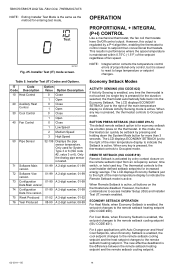
... default remote setback option is for the duration selected, the thermostat automatically falls back into the Economy Setback. However, this mode, the thermostat can quickly be setback by a P+I ) CONTROL Like a mechanical thermostat, the fan coil thermostats have On/Off control output. Installer Test (IT) Codes ... card key. In this output is regulated by pressing and holding down the System Mode button for increased energy savings. TB6575/TB8575 DIGITAL FAN COIL THERMOSTATS NOTE: Exiting Installer Test Mode is the same as the method for System Type 3 or 6 (ISU code #2, value 3 ...
... default remote setback option is for the duration selected, the thermostat automatically falls back into the Economy Setback. However, this mode, the thermostat can quickly be setback by a P+I ) CONTROL Like a mechanical thermostat, the fan coil thermostats have On/Off control output. Installer Test (IT) Codes ... card key. In this output is regulated by pressing and holding down the System Mode button for increased energy savings. TB6575/TB8575 DIGITAL FAN COIL THERMOSTATS NOTE: Exiting Installer Test Mode is the same as the method for System Type 3 or 6 (ISU code #2, value 3 ...
Installation Instructions
Page 15
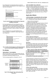
... Changeover with heat and cool setpoints. Logic for 2 Pipes with Single Setpoint and Economy Setback Deadband Illustration Fan Modes VERSASPEED™ FAN RAMPING When the fan switch is enabled for 4-pipe single setpoint auto changeover. TB6575/TB8575 DIGITAL FAN COIL THERMOSTATS Fig. 26 illustrates the relationship between the two thresholds, the valve output will be available. Fig...
... Changeover with heat and cool setpoints. Logic for 2 Pipes with Single Setpoint and Economy Setback Deadband Illustration Fan Modes VERSASPEED™ FAN RAMPING When the fan switch is enabled for 4-pipe single setpoint auto changeover. TB6575/TB8575 DIGITAL FAN COIL THERMOSTATS Fig. 26 illustrates the relationship between the two thresholds, the valve output will be available. Fig...
Installation Instructions
Page 16
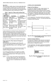
...setpoint. NOTE: For the 2 Pipe with Auxiliary Heat applications, the thermostat will occur every 2 hours to double check the water temperature. During this time, the valve (W/Y) will energize and the fan and auxiliary heat (Y/A) will also occur anytime the installer setup or installer...After Purge Heat Mode Cool Mode > Threshold Valve (W/Y) Changeover. Mode changes to change the setpoint. TB6575/TB8575 DIGITAL FAN COIL THERMOSTATS Operation: After exiting the installer setup, the thermostat will go into "Heat" or "Cool". The switching differential is defined via ISU code #10.
...setpoint. NOTE: For the 2 Pipe with Auxiliary Heat applications, the thermostat will occur every 2 hours to double check the water temperature. During this time, the valve (W/Y) will energize and the fan and auxiliary heat (Y/A) will also occur anytime the installer setup or installer...After Purge Heat Mode Cool Mode > Threshold Valve (W/Y) Changeover. Mode changes to change the setpoint. TB6575/TB8575 DIGITAL FAN COIL THERMOSTATS Operation: After exiting the installer setup, the thermostat will go into "Heat" or "Cool". The switching differential is defined via ISU code #10.
Installation Instructions
Page 17
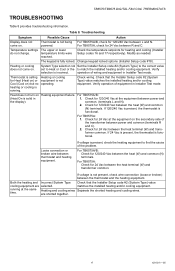
...installed heating and/or cooling equipment. are selected. Symptom Possible Cause Action Display does not come on. Check for 24 Vac between the thermostat and the heating equipment. For TB6575A/B: Check for heating and cooling (Installer Setup codes 16 and 17 respectively). heating or cooling is...(System Type) value matches the installed heating and/or cooling equipment. For TB6575A/B: (Heat On is functional. running . TB6575/TB8575 DIGITAL FAN COIL THERMOSTATS TROUBLESHOOTING Table 8 provides troubleshooting information. If 120/240 Vac is present, the...
...installed heating and/or cooling equipment. are selected. Symptom Possible Cause Action Display does not come on. Check for 24 Vac between the thermostat and the heating equipment. For TB6575A/B: Check for heating and cooling (Installer Setup codes 16 and 17 respectively). heating or cooling is...(System Type) value matches the installed heating and/or cooling equipment. For TB6575A/B: (Heat On is functional. running . TB6575/TB8575 DIGITAL FAN COIL THERMOSTATS TROUBLESHOOTING Table 8 provides troubleshooting information. If 120/240 Vac is present, the...
Installation Instructions
Page 18
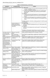
... turn on Wiring or connection in the Cool configured. Check for 120/240 Vac between thermostat and cooling equipment. If 24 Vac is present, the thermostat is not in 1. Fan does not turn Cooling equipment failure. Heating equipment is solid in the display). Set the... code #2 (System Type) value matches the installed heating and/or cooling equipment. Setup code #2) is not in the display. TB6575/TB8575 DIGITAL FAN COIL THERMOSTATS Table 8. common, (terminals L and N). 2. failure Check wiring and make sure the connection is correct. not activate Make sure the NO...
... turn on Wiring or connection in the Cool configured. Check for 120/240 Vac between thermostat and cooling equipment. If 24 Vac is present, the thermostat is not in 1. Fan does not turn Cooling equipment failure. Heating equipment is solid in the display). Set the... code #2 (System Type) value matches the installed heating and/or cooling equipment. Setup code #2) is not in the display. TB6575/TB8575 DIGITAL FAN COIL THERMOSTATS Table 8. common, (terminals L and N). 2. failure Check wiring and make sure the connection is correct. not activate Make sure the NO...
Installation Instructions
Page 19
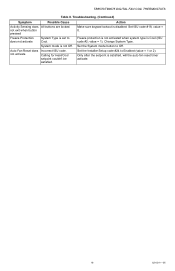
... when system type is disabled. Set ISU code #18, value = 0. Set the Installer Setup code #24 to Off. TB6575/TB8575 DIGITAL FAN COIL THERMOSTATS Table 8. Auto Fan Reset does not activate Incorrect ISU code. not exit when button pressed Make sure keypad lockout is Cool (ISU code #2; System mode is... satisfied, will the auto fan reset timer activate. 19 62-0311-05 Set the System mode button to Enabled (value = 1 or 2). Calling for Heat/Cool setpoint couldn...
... when system type is disabled. Set ISU code #18, value = 0. Set the Installer Setup code #24 to Off. TB6575/TB8575 DIGITAL FAN COIL THERMOSTATS Table 8. Auto Fan Reset does not activate Incorrect ISU code. not exit when button pressed Make sure keypad lockout is Cool (ISU code #2; System mode is... satisfied, will the auto fan reset timer activate. 19 62-0311-05 Set the System mode button to Enabled (value = 1 or 2). Calling for Heat/Cool setpoint couldn...

Installation Instructions
Page 20
Registered Trademark © 2010 Honeywell International Inc. 62-0311-05 M.S. Rev. 10-10 Printed in U.S.A. TB6575/TB8575 DIGITAL FAN COIL THERMOSTATS Automation and Control Solutions Honeywell International Inc. 1985 Douglas Drive North Golden Valley, MN 55422 Honeywell Limited-Honeywell Limitée 35 Dynamic Drive Toronto, Ontario M1V 4Z9 customer.honeywell.com ® U.S.
Registered Trademark © 2010 Honeywell International Inc. 62-0311-05 M.S. Rev. 10-10 Printed in U.S.A. TB6575/TB8575 DIGITAL FAN COIL THERMOSTATS Automation and Control Solutions Honeywell International Inc. 1985 Douglas Drive North Golden Valley, MN 55422 Honeywell Limited-Honeywell Limitée 35 Dynamic Drive Toronto, Ontario M1V 4Z9 customer.honeywell.com ® U.S.


