
Owner's Manual
Page 2
This allows you have questions, call Honeywell Inc. The Honeywell name is replacing a control that contains mercury in a sealed tube, do not place your new Honeywell thermostat. Recycling Notice M3375 This control contains mercury in the trash at 1-800-468-1502. 2 69-0563-2 Contact your local waste management authority for years ...
This allows you have questions, call Honeywell Inc. The Honeywell name is replacing a control that contains mercury in a sealed tube, do not place your new Honeywell thermostat. Recycling Notice M3375 This control contains mercury in the trash at 1-800-468-1502. 2 69-0563-2 Contact your local waste management authority for years ...
Owner's Manual
Page 9
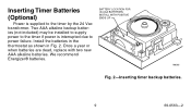
Install the batteries in the thermostat as shown in Fig. 2. BATTERY LOCATION FOR (2) AAA BATTERIES; Once a year or when batteries are dead, replace with two new AAA alkaline batteries. INSTALL WITH POSITIVE ENDS UP M8585 Fig. 2-Inserting timer backup batteries. 9 69-0563-2 We recommend Energizer® batteries. Two AAA alkaline backup batteries (not included) may be installed to supply power to the timer if power is supplied to power failure. Inserting Timer Batteries (Optional) Power is interrupted due to the timer by the 24 Vac transformer.
Install the batteries in the thermostat as shown in Fig. 2. BATTERY LOCATION FOR (2) AAA BATTERIES; Once a year or when batteries are dead, replace with two new AAA alkaline batteries. INSTALL WITH POSITIVE ENDS UP M8585 Fig. 2-Inserting timer backup batteries. 9 69-0563-2 We recommend Energizer® batteries. Two AAA alkaline backup batteries (not included) may be installed to supply power to the timer if power is supplied to power failure. Inserting Timer Batteries (Optional) Power is interrupted due to the timer by the 24 Vac transformer.
Owner's Manual
Page 14
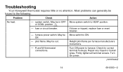
...in OFF or COOL position. 1 - Check for correct terminal hookups. May be out. furnace power switch. fuse or circuit breaker. If blown or tripped, replace fuse or reset breaker. - Turn On power. (continued) 14 69-0563-2 Move system switch to furnace. R and W thermostat connections. Firmly tighten all ... any frayed or broken wires. Most problems can generally be Move switch to the following: Problem Check Action No heat. - Troubleshooting Your Honeywell thermostat requires little or no attention. system switch. May be traced to ON. Turn Off power to HEAT position.
...in OFF or COOL position. 1 - Check for correct terminal hookups. May be out. furnace power switch. fuse or circuit breaker. If blown or tripped, replace fuse or reset breaker. - Turn On power. (continued) 14 69-0563-2 Move system switch to furnace. R and W thermostat connections. Firmly tighten all ... any frayed or broken wires. Most problems can generally be Move switch to the following: Problem Check Action No heat. - Troubleshooting Your Honeywell thermostat requires little or no attention. system switch. May be traced to ON. Turn Off power to HEAT position.
Owner's Manual
Page 17
... Off. Repair any frayed or broken wires. Power. Turn Off power to cooling system. Y and R thermostat connections. - Make sure power is blown or breaker tripped, replace or reset. Located outdoors and may be in OFF or HEAT position. - system switch. May be turned OFF. - condenser switch position. May be interrupted. Firmly...
... Off. Repair any frayed or broken wires. Power. Turn Off power to cooling system. Y and R thermostat connections. - Make sure power is blown or breaker tripped, replace or reset. Located outdoors and may be in OFF or HEAT position. - system switch. May be turned OFF. - condenser switch position. May be interrupted. Firmly...
Owner's Manual
Page 18
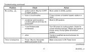
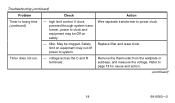
Wire separate transformer to page 19 for cause and action. (continued) 18 69-0563-2 Timer does not run. - Replace filter and reset clock. Remove the thermostat from the wallplate or subbase, and measure the voltage. filter. Refer to power clock. If clock powered through system transformer, power to system. - Safety limit on equipment may cut off power to clock and equipment may be clogged. Troubleshooting (continued) Problem Timer is losing time (continued). high limit control. Check Action - voltage across the C and R terminals. May be Off on safety.
Wire separate transformer to page 19 for cause and action. (continued) 18 69-0563-2 Timer does not run. - Replace filter and reset clock. Remove the thermostat from the wallplate or subbase, and measure the voltage. filter. Refer to power clock. If clock powered through system transformer, power to system. - Safety limit on equipment may cut off power to clock and equipment may be clogged. Troubleshooting (continued) Problem Timer is losing time (continued). high limit control. Check Action - voltage across the C and R terminals. May be Off on safety.
Owner's Manual
Page 20
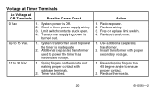
.... 20 69-0563-2 Transformer supplying power is burned out. Additional (separate) transformer used to 30 Vac. 1. Restore power. 2. Free or replace limit switch. 4. Install transformer with subbase terminals. 2. Short in timer power supply wiring. 3. Limit switch contacts stuck open. 4. Spring fingers on thermostat not making proper ... degree angle to 15 Vac. 1. Voltage at Timer Terminals Ac Voltage at C-R Terminals Possible Cause Check 0 Vac 1. Timer has failed. Up to ensure proper contact. 2. Replace wiring. 3.
.... 20 69-0563-2 Transformer supplying power is burned out. Additional (separate) transformer used to 30 Vac. 1. Restore power. 2. Free or replace limit switch. 4. Install transformer with subbase terminals. 2. Short in timer power supply wiring. 3. Limit switch contacts stuck open. 4. Spring fingers on thermostat not making proper ... degree angle to 15 Vac. 1. Voltage at Timer Terminals Ac Voltage at C-R Terminals Possible Cause Check 0 Vac 1. Timer has failed. Up to ensure proper contact. 2. Replace wiring. 3.
Owner's Manual
Page 21
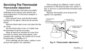
Remove thermostat cover and open the flipup cover. Replace thermostat cover and put the system into operation. Allow at the factory and should only need adjustment if it until both thermometers read the same. ... at least five minutes for cover thermometer to touch thermometer or breathe on a table near thermometer of known accuracy. If the readings are the same, replace cover and put the system into operation. Set the thermostat cover on it.
Remove thermostat cover and open the flipup cover. Replace thermostat cover and put the system into operation. Allow at the factory and should only need adjustment if it until both thermometers read the same. ... at least five minutes for cover thermometer to touch thermometer or breathe on a table near thermometer of known accuracy. If the readings are the same, replace cover and put the system into operation. Set the thermostat cover on it.

Owner's Manual
Page 23
... (i) return it, with proof of purchase (including date of purchase) and a short description of the malfunction, and mail it is defective or malfunctions, Honeywell shall repair or replace it (at any questions concerning this limitation may not apply to you . box 524, Minneapolis, MN 55440-0524 or call 1-800-468-1502, Monday... RESULTING, DIRECTLY OR INDIRECTLY FROM ANY BREACH OF ANY WARRANTY, EXPRESS OR IMPLIED, OR ANY OTHER FAILURE OF THIS PRODUCT. Limited One-Year Warranty Honeywell warrants this product to be to repair or replace the product within a reasonable period of time.
... (i) return it, with proof of purchase (including date of purchase) and a short description of the malfunction, and mail it is defective or malfunctions, Honeywell shall repair or replace it (at any questions concerning this limitation may not apply to you . box 524, Minneapolis, MN 55440-0524 or call 1-800-468-1502, Monday... RESULTING, DIRECTLY OR INDIRECTLY FROM ANY BREACH OF ANY WARRANTY, EXPRESS OR IMPLIED, OR ANY OTHER FAILURE OF THIS PRODUCT. Limited One-Year Warranty Honeywell warrants this product to be to repair or replace the product within a reasonable period of time.
Installation Instructions
Page 1
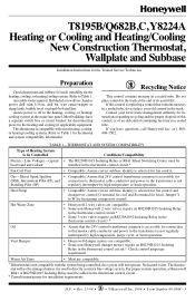
... will not operate. D.F. • Rev. 11-94 • 1 • ©Honeywell Inc. 1994 • Form Number6699--00556644--3 M3375 Assemble tools required: flat bladed screwdriver, hand...connection to thermostat cable conductor and power to directly control a line voltage system. T8195B/Q682B,C, Y8224A Heating or Cooling and Heating/Cooling New Construction Thermostat, Wallplate and ... is accessible for instructions regarding recycling and the proper disposal of this control is replacing a control that 24V control transformer common is not Standing Pilot (SP) regularly...
... will not operate. D.F. • Rev. 11-94 • 1 • ©Honeywell Inc. 1994 • Form Number6699--00556644--3 M3375 Assemble tools required: flat bladed screwdriver, hand...connection to thermostat cable conductor and power to directly control a line voltage system. T8195B/Q682B,C, Y8224A Heating or Cooling and Heating/Cooling New Construction Thermostat, Wallplate and ... is accessible for instructions regarding recycling and the proper disposal of this control is replacing a control that 24V control transformer common is not Standing Pilot (SP) regularly...
Installation Instructions
Page 4
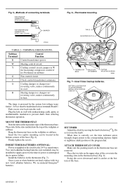
... in heat. B Heating damper or changeover/ reversing valve, makes continuously in cool. Insert the two captive mounting screws located in the thermostat base are dead, replace with nonhardening caulk, putty, or nonflammable insulation to power failure. Two AAA alkaline backup batteries (not included) may be maintained across terminals R and C. We recommend...
... in heat. B Heating damper or changeover/ reversing valve, makes continuously in cool. Insert the two captive mounting screws located in the thermostat base are dead, replace with nonhardening caulk, putty, or nonflammable insulation to power failure. Two AAA alkaline backup batteries (not included) may be maintained across terminals R and C. We recommend...


