
Owner's Manual
Page 2
... control in a sealed tube. Do not place control in a sealed tube, do not place your home one or more times every 24 hours. The Honeywell name is replacing a control that contains mercury in the trash at 1-800-468-1502. 2 69-0563-2 This thermostat meets California Title 24 requirements-mandatory installation of automatic setback...
... control in a sealed tube. Do not place control in a sealed tube, do not place your home one or more times every 24 hours. The Honeywell name is replacing a control that contains mercury in the trash at 1-800-468-1502. 2 69-0563-2 This thermostat meets California Title 24 requirements-mandatory installation of automatic setback...
Owner's Manual
Page 9
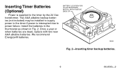
We recommend Energizer® batteries. BATTERY LOCATION FOR (2) AAA BATTERIES; INSTALL WITH POSITIVE ENDS UP M8585 Fig. 2-Inserting timer backup batteries. 9 69-0563-2 Two AAA alkaline backup batteries (not included) may be installed to supply power to the timer if power is supplied to power failure. Install the batteries in the thermostat as shown in Fig. 2. Once a year or when batteries are dead, replace with two new AAA alkaline batteries. Inserting Timer Batteries (Optional) Power is interrupted due to the timer by the 24 Vac transformer.
We recommend Energizer® batteries. BATTERY LOCATION FOR (2) AAA BATTERIES; INSTALL WITH POSITIVE ENDS UP M8585 Fig. 2-Inserting timer backup batteries. 9 69-0563-2 Two AAA alkaline backup batteries (not included) may be installed to supply power to the timer if power is supplied to power failure. Install the batteries in the thermostat as shown in Fig. 2. Once a year or when batteries are dead, replace with two new AAA alkaline batteries. Inserting Timer Batteries (Optional) Power is interrupted due to the timer by the 24 Vac transformer.
Owner's Manual
Page 14
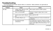
.... Turn Off power to HEAT position. May be traced to ON. Turn On power. (continued) 14 69-0563-2 Off. - R and W thermostat connections. system switch. Most problems can generally be Move switch to the following: Problem Check Action No heat. - Relight pilot flame per furnace manufacturers ...instructions. - Firmly tighten all terminal screws. fuse or circuit breaker. May be in OFF or COOL position. 1 - Troubleshooting Your Honeywell thermostat requires little or no attention. If blown or tripped, replace fuse or reset breaker. -
.... Turn Off power to HEAT position. May be traced to ON. Turn On power. (continued) 14 69-0563-2 Off. - R and W thermostat connections. system switch. Most problems can generally be Move switch to the following: Problem Check Action No heat. - Relight pilot flame per furnace manufacturers ...instructions. - Firmly tighten all terminal screws. fuse or circuit breaker. May be in OFF or COOL position. 1 - Troubleshooting Your Honeywell thermostat requires little or no attention. If blown or tripped, replace fuse or reset breaker. -
Owner's Manual
Page 17
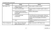
... turned OFF. - condenser switch position. Make sure power is blown or breaker tripped, replace or reset. Reset clock. (continued) 17 69-0563-2 Turn Off power to COOL position. Contact a qualified service technician for correct terminal hookups. system switch. Y and R thermostat connections. - Power. Action Move switch to cooling system. If fuse is Off...
... turned OFF. - condenser switch position. Make sure power is blown or breaker tripped, replace or reset. Reset clock. (continued) 17 69-0563-2 Turn Off power to COOL position. Contact a qualified service technician for correct terminal hookups. system switch. Y and R thermostat connections. - Power. Action Move switch to cooling system. If fuse is Off...
Owner's Manual
Page 18
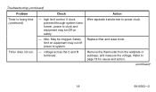
Wire separate transformer to system. - Remove the thermostat from the wallplate or subbase, and measure the voltage. Troubleshooting (continued) Problem Timer is losing time (continued). Replace filter and reset clock. filter. Safety limit on safety. If clock powered through system transformer, power to page 19 for cause and action. (continued) 18 69-0563-2 voltage across the C and R terminals. Refer to clock and equipment may be clogged. Check Action - high limit control. Timer does not run. - May be Off on equipment may cut off power to power clock.
Wire separate transformer to system. - Remove the thermostat from the wallplate or subbase, and measure the voltage. Troubleshooting (continued) Problem Timer is losing time (continued). Replace filter and reset clock. filter. Safety limit on safety. If clock powered through system transformer, power to page 19 for cause and action. (continued) 18 69-0563-2 voltage across the C and R terminals. Refer to clock and equipment may be clogged. Check Action - high limit control. Timer does not run. - May be Off on equipment may cut off power to power clock.
Owner's Manual
Page 20
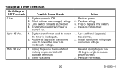
...timer is inadequate. 2. Restore power. 2. Free or replace limit switch. 4. Limit switch contacts stuck open. 4. Action 1. System power is burned out. Replace wiring. 3. Spring fingers on thermostat not making proper contact with proper secondary voltage. 1. ...Voltage at Timer Terminals Ac Voltage at C-R Terminals Possible Cause Check 0 Vac 1. Use additional (separate) transformer. 2. Short in timer power supply wiring. 3. Up to 30 Vac. 1. Replace thermostat...
...timer is inadequate. 2. Restore power. 2. Free or replace limit switch. 4. Limit switch contacts stuck open. 4. Action 1. System power is burned out. Replace wiring. 3. Spring fingers on thermostat not making proper contact with proper secondary voltage. 1. ...Voltage at Timer Terminals Ac Voltage at C-R Terminals Possible Cause Check 0 Vac 1. Use additional (separate) transformer. 2. Short in timer power supply wiring. 3. Up to 30 Vac. 1. Replace thermostat...
Owner's Manual
Page 21
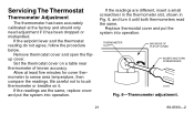
... thermometers read the same. If the readings are the same, replace cover and put the system into operation. Be careful not to sense area temperature, then compare the readings. Replace thermostat cover and put the system into operation. If the setpoint lever and the thermostat reading do not agree, follow the procedure below. Remove...
... thermometers read the same. If the readings are the same, replace cover and put the system into operation. Be careful not to sense area temperature, then compare the readings. Replace thermostat cover and put the system into operation. If the setpoint lever and the thermostat reading do not agree, follow the procedure below. Remove...
Installation Instructions
Page 1
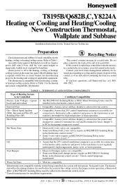
... are compatible. • Some non-Honeywell damper motors require an R8239D1015 Isolating Relay in the trash at the end of this control is replacing a control that 24V control transformer common is accessible for the Trained Service Technician. T8195B/Q682B,C, Y8224A Heating or Cooling and Heating/Cooling New Construction Thermostat, Wallplate and Subbase Installation Instructions...
... are compatible. • Some non-Honeywell damper motors require an R8239D1015 Isolating Relay in the trash at the end of this control is replacing a control that 24V control transformer common is accessible for the Trained Service Technician. T8195B/Q682B,C, Y8224A Heating or Cooling and Heating/Cooling New Construction Thermostat, Wallplate and Subbase Installation Instructions...
Installation Instructions
Page 4
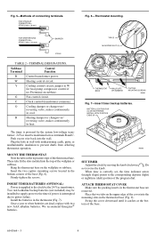
...; batteries. BATTERY LOCATION FOR (2) AAA BATTERIES; ATTACH THERMOSTAT COVER Make sure the packing inserts in the thermostat base are dead, replace with nonhardening caulk, putty, or nonflammable insulation to prevent drafts from affecting thermostat operation. C Clock control (transformer common). O Cooling ...-Vac transformer. TAB (2) MOUNTING SLOT (2) 4 3 2 1 12 5 9 8 76 11 10 9 8 7 10 12 11 6 THERMOSTAT BASE WALLPLATE OR SUBBASE CAPTIVE MOUNTING SCREWS M8603 Fig. 7-Insert timer backup batteries. G Fan control circuit. Push excess wire back into the top...
...; batteries. BATTERY LOCATION FOR (2) AAA BATTERIES; ATTACH THERMOSTAT COVER Make sure the packing inserts in the thermostat base are dead, replace with nonhardening caulk, putty, or nonflammable insulation to prevent drafts from affecting thermostat operation. C Clock control (transformer common). O Cooling ...-Vac transformer. TAB (2) MOUNTING SLOT (2) 4 3 2 1 12 5 9 8 76 11 10 9 8 7 10 12 11 6 THERMOSTAT BASE WALLPLATE OR SUBBASE CAPTIVE MOUNTING SCREWS M8603 Fig. 7-Insert timer backup batteries. G Fan control circuit. Push excess wire back into the top...


