
Installation Instructions
Page 3
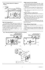
...or subbase mounting holes on horizontal outlet box. NOTE: All wiring must comply with two screws. For heating-only systems, connect wires to the Typical Wiring Diagrams section at the end of this publication. Push excess wire back into the wall. Subbase (Heating/Cooling Systems) Refer... to Fig. 5, and strip the thermostat wire insulation as necessary. Carefully level the wallplate...
...or subbase mounting holes on horizontal outlet box. NOTE: All wiring must comply with two screws. For heating-only systems, connect wires to the Typical Wiring Diagrams section at the end of this publication. Push excess wire back into the wall. Subbase (Heating/Cooling Systems) Refer... to Fig. 5, and strip the thermostat wire insulation as necessary. Carefully level the wallplate...
Installation Instructions
Page 6
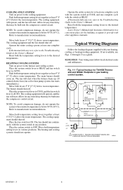
... both levers 5° F [3° C] above room temperature. The cooling equipment will operate, and the fan will start. Allow for T8195B Thermostat and Q682C Wallplate in gas heating control system. NOTE: To avoid compressor damage, do not operate the system when outdoor temperature is ... at least 5° F [3° C] above the room temperature. The heating and cooling systems should shut off. Typical Wiring Diagrams Follow the hookup diagram supplied with other appliance manuals. Allow for at least one complete cycle with the switch at COOL and one complete cycle. The...
... both levers 5° F [3° C] above room temperature. The cooling equipment will operate, and the fan will start. Allow for T8195B Thermostat and Q682C Wallplate in gas heating control system. NOTE: To avoid compressor damage, do not operate the system when outdoor temperature is ... at least 5° F [3° C] above the room temperature. The heating and cooling systems should shut off. Typical Wiring Diagrams Follow the hookup diagram supplied with other appliance manuals. Allow for at least one complete cycle with the switch at COOL and one complete cycle. The...


