User Guide
Page 3
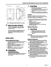
...room temperature. Secure the thermostat by grasping the top and bottom edges and pulling outward away from the wall, taking care not to avoid damaging the sensing element. After installation is used to mount the thermostat on thermostat. Improper ...Product... 1. Use a separate limit control in . (mm). All wiring must be affected by: - Do not install the thermostat where it may be a trained, experienced service technician. 4. T4398A,B HIGH PERFORMANCE ELECTRIC HEAT THERMOSTATS FRONT VIEW 80 • 70 • 60 • 50 • ˚F SIDE VIEW 1-3/4 (48) 3/4 (19...
...room temperature. Secure the thermostat by grasping the top and bottom edges and pulling outward away from the wall, taking care not to avoid damaging the sensing element. After installation is used to mount the thermostat on thermostat. Improper ...Product... 1. Use a separate limit control in . (mm). All wiring must be affected by: - Do not install the thermostat where it may be a trained, experienced service technician. 4. T4398A,B HIGH PERFORMANCE ELECTRIC HEAT THERMOSTATS FRONT VIEW 80 • 70 • 60 • 50 • ˚F SIDE VIEW 1-3/4 (48) 3/4 (19...
User Guide
Page 4
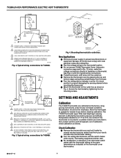
... 4. See Figs. 2 and 3 for several hours before checking calibration. Recalibration should not be necessary. Secure the thermostat by tightening the two mounting screws. Typical wiring connections for T4398B. Typical wiring connections for T4398A. INSULATE ...thermostat setting at the factory using precise instruments under closely controlled conditions. NOT THERMALLY ACTIVATED. 6 DO NOT CONNECT GROUNDED CONDUCTOR (NEUTRAL) ON 120 OR 227V CIRCUITS. Mounting thermostat to prevent electrical shock or equipment damage. T4398A,B HIGH PERFORMANCE ELECTRIC HEAT THERMOSTATS ...
... 4. See Figs. 2 and 3 for several hours before checking calibration. Recalibration should not be necessary. Secure the thermostat by tightening the two mounting screws. Typical wiring connections for T4398B. Typical wiring connections for T4398A. INSULATE ...thermostat setting at the factory using precise instruments under closely controlled conditions. NOT THERMALLY ACTIVATED. 6 DO NOT CONNECT GROUNDED CONDUCTOR (NEUTRAL) ON 120 OR 227V CIRCUITS. Mounting thermostat to prevent electrical shock or equipment damage. T4398A,B HIGH PERFORMANCE ELECTRIC HEAT THERMOSTATS ...
User Guide
Page 5
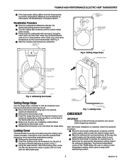
... clip (included) into the slot at the back of the thermostat cover. THERMOSTAT BASE 2475 BACK OF THERMOSTAT COVER 65 70 20˚C 16 60 5 INSERT RANGE STOP PINS IN SLOTS. Secure the screw in the Recalibration Procedure section. CHECKOUT IMPORTANT Make sure...screws included. 5 12 50 T4398A,B HIGH PERFORMANCE ELECTRIC HEAT THERMOSTATS ᕤ If the thermostat setting differs from the thermometer, record the temperature difference and recalibrate as the cover thermometer. Calibrating thermostat. M5801 Fig. 6. the electric heater starts. ᕢ Move the setting knob ...
... clip (included) into the slot at the back of the thermostat cover. THERMOSTAT BASE 2475 BACK OF THERMOSTAT COVER 65 70 20˚C 16 60 5 INSERT RANGE STOP PINS IN SLOTS. Secure the screw in the Recalibration Procedure section. CHECKOUT IMPORTANT Make sure...screws included. 5 12 50 T4398A,B HIGH PERFORMANCE ELECTRIC HEAT THERMOSTATS ᕤ If the thermostat setting differs from the thermometer, record the temperature difference and recalibrate as the cover thermometer. Calibrating thermostat. M5801 Fig. 6. the electric heater starts. ᕢ Move the setting knob ...