Installation Instructions
Page 3
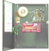
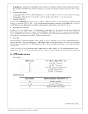
... NC terminals from 2nd unit and so on next page... 3 Connect the Battery Fail output "Form C" dry contacts to latch ON until manually reset. NOTE: For UL603 or UL294 applications use the battery link provided to the monitoring device. DC power failure Red LED - Cascade Connection...be connected together as shown in series. AC present Red LED - L6 L7 Distribution Board Status When Lit Red LED - FACP alarm activated HP400ULM Installation Document P/N 52390:A 1/05/06 Continued on for each new addition. Install the 2.2K Ohm (EOL) resistor provided at a Key Switch...
... NC terminals from 2nd unit and so on next page... 3 Connect the Battery Fail output "Form C" dry contacts to latch ON until manually reset. NOTE: For UL603 or UL294 applications use the battery link provided to the monitoring device. DC power failure Red LED - Cascade Connection...be connected together as shown in series. AC present Red LED - L6 L7 Distribution Board Status When Lit Red LED - FACP alarm activated HP400ULM Installation Document P/N 52390:A 1/05/06 Continued on for each new addition. Install the 2.2K Ohm (EOL) resistor provided at a Key Switch...