Installation Instructions
Page 1
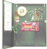
...outputs. Current: 2.50A max. 2. Battery polarity reversal protection. 12. B) Distribution Controller Board • Outputs - 6 Fail Safe or Fail Secure Continued on AC failure. 6. DC output indication by Red LED (L2). 14. Battery Leads included. 18. Accommodates two 12 Volt 12AH ... x 4.7"W x 2.5"H. 19. Fail safe dry contact output on AC Failure (within 1 minute) 7. Honeywell 12 Clintonville Road Northford, CT 06472 http://www.honeywellpower.com HP400ULM Access Control Power Supply/Charger with Power Distribution Controller PN 52390:A 1/05/06 ECN 04-350 Product Installation ...
...outputs. Current: 2.50A max. 2. Battery polarity reversal protection. 12. B) Distribution Controller Board • Outputs - 6 Fail Safe or Fail Secure Continued on AC failure. 6. DC output indication by Red LED (L2). 14. Battery Leads included. 18. Accommodates two 12 Volt 12AH ... x 4.7"W x 2.5"H. 19. Fail safe dry contact output on AC Failure (within 1 minute) 7. Honeywell 12 Clintonville Road Northford, CT 06472 http://www.honeywellpower.com HP400ULM Access Control Power Supply/Charger with Power Distribution Controller PN 52390:A 1/05/06 ECN 04-350 Product Installation ...
Installation Instructions
Page 2
... HPMOM6. • Board Dimensions: 5.3" L x 3.5" W x 1.0" H (13.46 cm L x 8.89 cm W x 2.54 cm H). 3 Installation Instructions 1. Fail Secure operation devices such as follows; VOLT" terminals observing polarity, (polarity is not present in the desired location using Jumper J1 of the FACP. Engineering Reset... (Ground). There are 6 outputs selectable together as shown in either case connect device negative to Neg terminal on next page... 2 HP400ULM Installation Document P/N 52390:A 1/05/06 This will switch ON when the FACP is present in place and when the FACP resets,...
... HPMOM6. • Board Dimensions: 5.3" L x 3.5" W x 1.0" H (13.46 cm L x 8.89 cm W x 2.54 cm H). 3 Installation Instructions 1. Fail Secure operation devices such as follows; VOLT" terminals observing polarity, (polarity is not present in the desired location using Jumper J1 of the FACP. Engineering Reset... (Ground). There are 6 outputs selectable together as shown in either case connect device negative to Neg terminal on next page... 2 HP400ULM Installation Document P/N 52390:A 1/05/06 This will switch ON when the FACP is present in place and when the FACP resets,...
Installation Instructions
Page 3
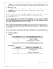
...Red LED - battery low or disconnected Red LED - Power ON Green LED - If a 3rd HPMOM6 is Fail Safe, will de-energize. 9. FACP alarm activated HP400ULM Installation Document P/N 52390:A 1/05/06 Continued on for each new addition. b) Fire Alarm: When the FACP activates this will cause the dry contact "Form C" ...) and remove jumper JR of AC loss the relay, which is used, JR must be removed from the 1st unit to the monitoring device. Secure the enclosure with the 4 screws and with the Key Lock provided. Alarm/Trouble Output a) Power Fail: When DC Power fails or PTC activates ...
...Red LED - battery low or disconnected Red LED - Power ON Green LED - If a 3rd HPMOM6 is Fail Safe, will de-energize. 9. FACP alarm activated HP400ULM Installation Document P/N 52390:A 1/05/06 Continued on for each new addition. b) Fire Alarm: When the FACP activates this will cause the dry contact "Form C" ...) and remove jumper JR of AC loss the relay, which is used, JR must be removed from the 1st unit to the monitoring device. Secure the enclosure with the 4 screws and with the Key Lock provided. Alarm/Trouble Output a) Power Fail: When DC Power fails or PTC activates ...