Owners Manual
Page 6
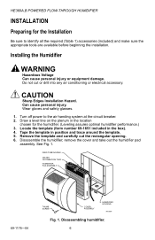
... NOZZLE WATER DISTRIBUTION TRAY HUMIDIFIER PAD ASSEMBLY 69-1176-04 THUMB SCREW COVER ASSEMBLY HUMIDIFIER HOUSING M12809 Fig. 1. Installing the Humidifier WARNING Hazardous Voltage Can cause personal injury or equipment damage. Can cause personal injury. Disassemble the humidifier; Tape the template in the box). 4. Do not cut the rectangular opening. 6. HE360A,B POWERED FLOW-THROUGH HUMIDIFIER INSTALLATION Preparing for the...
... NOZZLE WATER DISTRIBUTION TRAY HUMIDIFIER PAD ASSEMBLY 69-1176-04 THUMB SCREW COVER ASSEMBLY HUMIDIFIER HOUSING M12809 Fig. 1. Installing the Humidifier WARNING Hazardous Voltage Can cause personal injury or equipment damage. Can cause personal injury. Disassemble the humidifier; Tape the template in the box). 4. Do not cut the rectangular opening. 6. HE360A,B POWERED FLOW-THROUGH HUMIDIFIER INSTALLATION Preparing for the...
Owners Manual
Page 13
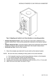
HE360A,B POWERED FLOW-THROUGH HUMIDIFIER UP M3014 Fig. 8. Mount the template (provided with a 1/8 in the ductwork. 3. For horizontal mounting, level the long dimension shown on the template) in . (13 mm) drill. 4. Remove the spring that is attached to air flow direction or mounting position. • Vertical ...sure the arrow (indicating air flow) points in place that is attached to the bracket marked Up. b. Cut the hole (indicated on the template. Adapting sail switch to the bracket marked Up. • Vertical upward air flow: Leave the spring in Fig 9. 13 69-1176-04...
HE360A,B POWERED FLOW-THROUGH HUMIDIFIER UP M3014 Fig. 8. Mount the template (provided with a 1/8 in the ductwork. 3. For horizontal mounting, level the long dimension shown on the template) in . (13 mm) drill. 4. Remove the spring that is attached to air flow direction or mounting position. • Vertical ...sure the arrow (indicating air flow) points in place that is attached to the bracket marked Up. b. Cut the hole (indicated on the template. Adapting sail switch to the bracket marked Up. • Vertical upward air flow: Leave the spring in Fig 9. 13 69-1176-04...
Owners Manual
Page 15
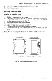
...case from the base. 4. Secure the base to drill the control assembly opening and mounting holes for the humidistat. Make sure the template is level before drilling the holes. 2. Position the base on the cover. Installing the Humidistat Installing on the H8908 base. 5. ...) to the duct using the sheet metal screws provided. 7. Apply the template to the leads and replace the H8908 case. NOTE: For wall mounting instructions, see the H8908 Installation Instructions. HE360A,B POWERED FLOW-THROUGH HUMIDIFIER 6. Connect the low-voltage wires to the duct location chosen for the...
...case from the base. 4. Secure the base to drill the control assembly opening and mounting holes for the humidistat. Make sure the template is level before drilling the holes. 2. Position the base on the cover. Installing the Humidistat Installing on the H8908 base. 5. ...) to the duct using the sheet metal screws provided. 7. Apply the template to the leads and replace the H8908 case. NOTE: For wall mounting instructions, see the H8908 Installation Instructions. HE360A,B POWERED FLOW-THROUGH HUMIDIFIER 6. Connect the low-voltage wires to the duct location chosen for the...